
 Hyundai Equus: Side Impact Sensor (SIS) Repair procedures
Second generation VI (2009–2026) / Hyundai Equus VI 2009-2026 Service Manual / Restraint / SRSCM / Side Impact Sensor (SIS) Repair procedures
Hyundai Equus: Side Impact Sensor (SIS) Repair procedures
Second generation VI (2009–2026) / Hyundai Equus VI 2009-2026 Service Manual / Restraint / SRSCM / Side Impact Sensor (SIS) Repair procedures
Second generation VI (2009–2026) / Hyundai Equus VI 2009-2026 Service Manual / Restraint / SRSCM / Side Impact Sensor (SIS) Repair procedures
| Removal |
|

Front Side Impact Sensor
| 1. |
Disconnect the battery negative cable, and wait for at least three minutes before beginning work. |
| 2. |
Remove the front door trim.
(Refer to Body - "Front Door Trim") |
| 3. |
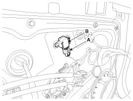
Disconnect the front side impact sensor connector (A), and
then remove the front side impact sensor mounting screws to remove the
sensor (B).
|
Rear Side Impact Sensor
| 1. |
Disconnect the battery negative cable and wait for at least three minutes before beginning work. |
| 2. |
Remove the rear wheel house trim.
(Refer to Body - " Rear Wheel House Trim") |
| 3. |
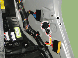
Disconnect the rear side impact sensor connector (A), and
then loosen the rear side impact sensor mounting bolt to remove the rear
side impact sensor (B).
|
| Installation |
Do not turn the ignition switch ON and do not connect the battery cable while replacing the side impact sensor.
|
Front Side Impact Sensor
| 1. |
Install the new front side impact sensor with the screws, then connect the front side impact sensor connector.
|
| 2. |
Install the front door trim.
(Refer to Body - "Front Door Trim") |
| 3. |
Reconnect the battery negative cable. |
| 4. |
After installing the front side impact sensor, confirm proper system operation:
Turn the ignition switch ON; the SRS indicator light should turn on for about six seconds and then go off. |
Rear Side Impact Sensor
| 1. |
Install the new rear side impact sensor with a bolt and then connect the rear side impact sensor connector.
|
| 2. |
Install the rear wheel house trim.
(Refer to Body - "Rear Wheel House Trim") |
| 3. |
Reconnect the battery negative cable. |
| 4. |
After installing the rear side impact sensor, confirm proper system operation:
Turn the ignition switch ON; the SRS indicator light should turn on for about six seconds and then go off. |
 Side Impact Sensor (SIS) Components and Components Location
Components
...
 Seat Belt Buckle Switch (BS) Description and Operation
Description
The SRSCM monitors the status of the driver and front
passenger seat belt buckle. The SRSCM provides one pin each for the
driver and front passenger seat belt buckle status input. T ...
See also:
Components and Components Location
Component Location
1. Windshield wiper arm & blade2. Wiper & washer switch3. Windshield washer hose4. Windshield wiper motor & linkage5. Washer motor6. Washer reservoir
...
Troubleshooting
Troubleshooting
Problem Symptoms Table
Before replacing or repairing air conditioning components,
first determine if the malfunction is due to the refrigerant charge, air
flow or compressor. ...
Fuel Pump Control Module (FPCM) Repair procedures
Inspection
1.
Connect the GDS on the Data Link Connector (DLC).
2.
Check the output voltage of fuel pressure sensor (FPS).
Specification: Refer to “Specification�
...
Categories
Hyundai Equus Manuals

© 2011-2026 Copyright www.heqmanual.com