 Hyundai Equus: Power Door Lock Actuators Repair procedures
Second generation VI (2009–2026) / Hyundai Equus VI 2009-2026 Service Manual / Body Electrical System / Power Door Locks / Power Door Lock Actuators Repair procedures
Hyundai Equus: Power Door Lock Actuators Repair procedures
Second generation VI (2009–2026) / Hyundai Equus VI 2009-2026 Service Manual / Body Electrical System / Power Door Locks / Power Door Lock Actuators Repair procedures
Second generation VI (2009–2026) / Hyundai Equus VI 2009-2026 Service Manual / Body Electrical System / Power Door Locks / Power Door Lock Actuators Repair procedures
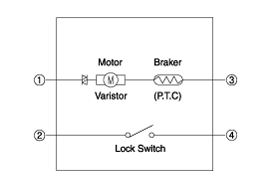
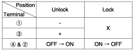
| Inspection |
Front Door Lock Module Inspection
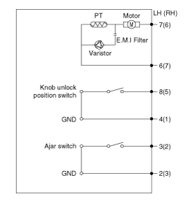
| 1. |
Remove the front door trim.
(Refer to Body - "Front Door Trim") |
| 2. |
Remove the front door module.
(Refer to Body - "Front Door Module") |
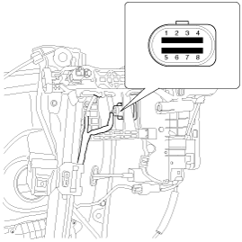
| 3. |
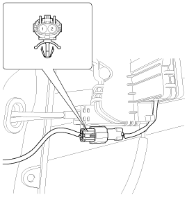
Disconnect the connectors from the actuator.
|
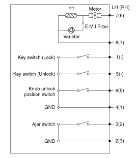
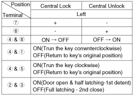
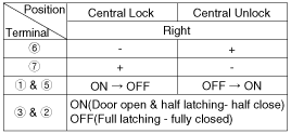
| 4. |
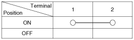
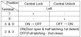
Check actuator operation by connecting power and ground
according to the table. To prevent damage to the actuator, apply battery
voltage only momentarily.
|
| 5. |
Disconnect the power ajar switch connector from door lock actuator.
|
| 6. |
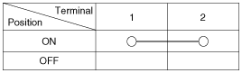
Check for continuity between terminals in half latching condition according to the table.
|
| 7. |
Operate the cinching reset procedure when power door latch operation (automatic full latching) is faulty.
|
Rear Door Lock Module Inspection
| 1. |
Remove the rear door trim.
(Refer to Body - "Rear Door Trim") |
| 2. |
Remove the rear door module.
(Refer to Body - "Rear Door Module") |
| 3. |
Disconnect the connectors from the actuator.
|
| 4. |
Check actuator operation by connecting power and ground
according to the table. To prevent damage to the actuator, apply battery
voltage only momentarily.
|
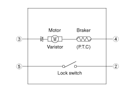
| 5. |
Disconnect the power ajar switch connector from door lock actuator.
|
| 6. |
Check for continuity between terminals in half latching condition according to the table.
|

| 7. |
Operate the cinching reset procedure when power door latch operation (automatic full latching) is faulty.
|
Trunk Lock Module Inspection
| 1. |
Remove the trunk trim.
(Refer to Body - "Trunk Trim") |
| 2. |
Disconnect the 4P connector from the actuator.
|
| 3. |
Check actuator operation by connecting power and ground
according to the table. To prevent damage to the actuator, apply battery
voltage only momentarily.
|
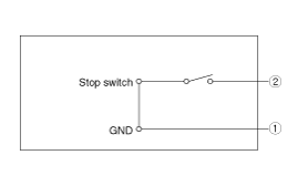
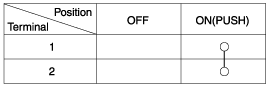
Trunk Open Switch
| 1. |
Check for continuity between the terminals in each switch position according to the table.
|
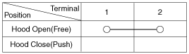
Hood Switch
| 1. |
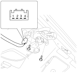
Disconnect the connector (A) and bolts from the hood switch.
|
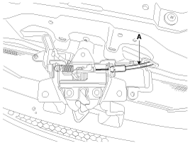
| 2. |
Check for continuity between the terminals and ground according to the table.
(Refer to Body - "Hood Latch")
|
 Description and Operation
Description
System Overview
The larger the size of the door, the harder it is to close
it. Quite often we see people driving with a door not completely closed.
Power door latch addresses the is ...
 Power Door Lock Switch Repair procedures
Inspection
Diagnosis With GDS
1.
It will be able to diagnose defects of DDM/ADM with GDS
quickly. GDS can operates actuator forcefully, input/output value
monitoring and self diagnosis.
2. ...
See also:
Climate Seat Unit Schematic Diagrams
Circuit Diagram
...
Specifications
Specifications
ItemsSpecificationRated voltageDC 12VOperating voltage9V ~ 16VOperating speed15x/h ~ 250x/hSensible distance70m (Sedan)Curvature radiusStart : More than 100mStop : Less than 70mFre ...
Crach Pad Center Panel Repair procedures
Replacement
•
Put on gloves to protect your hands.
•
When prying with a flat-tip screwdriver, wrap it with
protective tape, and apply p ...
Categories
Hyundai Equus Manuals

© 2011-2026 Copyright www.heqmanual.com