
 Hyundai Equus: Fuel Pump Repair procedures
Second generation VI (2009–2026) / Hyundai Equus VI 2009-2026 Service Manual / Engine Control/Fuel System / Fuel Delivery System / Fuel Pump Repair procedures
Hyundai Equus: Fuel Pump Repair procedures
Second generation VI (2009–2026) / Hyundai Equus VI 2009-2026 Service Manual / Engine Control/Fuel System / Fuel Delivery System / Fuel Pump Repair procedures
Second generation VI (2009–2026) / Hyundai Equus VI 2009-2026 Service Manual / Engine Control/Fuel System / Fuel Delivery System / Fuel Pump Repair procedures
| Removal |
| 1. |
Release the residual pressure in fuel line.
(Refer to Fuel Delivery System - "Release Residual Pressure in Fuel Line") |
| 2. |
Folding the rear seat cushion. |
| 3. |
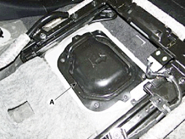
Remove the fuel pump service cover (A) after loosening the screws.
|
| 4. |
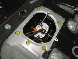
Disconnect the fuel pump connector (A) and fuel pressure connector (B).
|
| 5. |
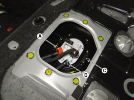
Disconnect the fuel feed tube quick-connector (A) and the suction hose (B). |
| 6. |
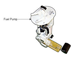
Remove the fuel pump from the fuel tank after removing the installation bolts (C).
|
| Installation |
| 1. |
Install in the reverse order of removal.
|

| Inspection |
| [Fuel sender] |
| 1. |
Turn ignition switch OFF and disconnect the negative (-)battery cable. |
| 2. |
Remove the fuel pump assembly.
(Refer to Fuel Delivery System - "Fuel Pump") |
| 3. |
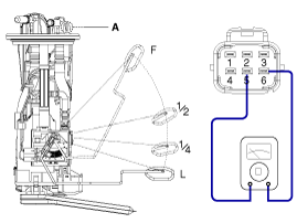
Using an ohmmeter, measure the resistance between terminals 5 and 6 of sender connector (A) at each float level.
|
| 4. |
Check that the resistance is within the specification.
|

| [Fuel pump three phase coil inspection] |
| 1. |
Turn ignition switch OFF and disconnect the negative (-)battery cable. |
| 2. |
Remove the fuel pump assembly.
(Refer to Fuel Delivery System - "Fuel Pump") |
| 3. |
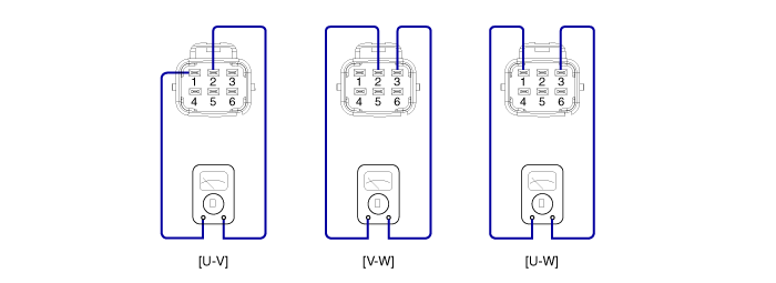
Using an ohmmeter, measure the resistance between terminals U-V, V-W, W-U. |
| 4. |
Check that the resistance is within the specification.
|
| [Fuel Pump] |
| 1. |
Turn ignition switch OFF and disconnect the negative (-)battery cable. |
| 2. |
Remove the fuel pump assembly.
(Refer to Fuel Delivery System - "Fuel Pump") |
| 3. |
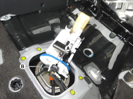
Connect the fuel pump connector (A) and fuel pressure sensor connector (B).
|
| 4. |
Reconnect the negative (-) battery cable. |
| 5. |
Turn ignition switch ON or cracking at the no-load state. |
| 6. |
Operate the fuel pump.
|
| 7. |
Check the normal state of the fuel pump. |
 Fuel Tank Repair procedures
Removal
1.
Release the residual pressure in fuel line.
(Refer to Fuel Delivery System - "Release Residual Pressure in Fuel Line")
2.
Turn the ignition switch OFF and disconnect the negative ...
 Sub Fuel Sender Repair procedures
Removal
1.
Release the residual pressure in fuel line.
(Refer to Fuel Delivery System - "Release Residual Pressure in Fuel Line")
2.
Folding the rear seat cushion.
3.
Remove the fuel pump ...
See also:
Tire chains
Tire chains, if necessary, should be installed on the drive wheels (rear wheels).
Be sure that the chains are installed in accordance with the manufacturer's instructions.
To minimize tire and c ...
Battery Replacement
If the Smart Key is not working properly, try replacing the battery with a new
one.
Battery Replacement of Conventional Smart Key
Battery Type: CR2032 To Replace the Battery:
1. Pry open the ...
Electronic Active Headrest Schematic Diagrams
Circuit Diagram
...
Categories
Hyundai Equus Manuals

© 2011-2026 Copyright www.heqmanual.com