
 Hyundai Equus: Fuel Tank Repair procedures
Second generation VI (2009–2026) / Hyundai Equus VI 2009-2026 Service Manual / Engine Control/Fuel System / Fuel Delivery System / Fuel Tank Repair procedures
Second generation VI (2009–2026) / Hyundai Equus VI 2009-2026 Service Manual / Engine Control/Fuel System / Fuel Delivery System / Fuel Tank Repair procedures
| Removal |
| 1. |
Release the residual pressure in fuel line.
(Refer to Fuel Delivery System - "Release Residual Pressure in Fuel Line") |
| 2. |
Turn the ignition switch OFF and disconnect the negative (-) battery cable. |
| 3. |
Folding the rear seat cushion. |
| 4. |
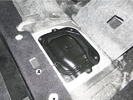
Remove the service cover (A) of the fuel pump after loosening the screws.
|
| 5. |
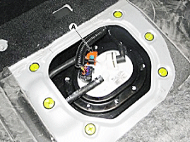
Disconnect the fuel feed tube quick - connector (A).
|
| 6. |
Remove the service cover of the canister (A) in trunk room.
|

| 7. |
Disconnect the vapor tube quick-connector (A).
|

| 8. |
Remove the rear - LH wheel, tire, and the inner wheel house, |
| 9. |
Disconnect the fuel tank extension connector (A), and then remove the wiring harness from the vehice.
|

| 10. |
Lift the vehice. |
| 11. |
Remove the center muffler.
(Refer to Engine Mechanical System - "Muffler") |
| 12. |
Remove the under cover (A).
|

| 13. |
Remove the propeller shaft.
(Refer to Driveshaft and acle - "Propeller Shaft Assembly") |
| 14. |
Disconnect the fuel filler hose (A) and leveling hose (B).
|

| 15. |
Support the fuel tank with jack (A).
|

| 16. |
Remove the fuel tank (B) from the vehicle arter removing the mounting nuts(A).
|

| Installation |
| 1. |
Install in the reverse order of removal.
|
 Repair procedures
Fuel Pressure Test
1.
Release the residual pressure in fuel line.
(Refer to Fuel Delivery System - "Release Residual Pressure in Fuel Line")
When removing the fuel pump re ...
 Fuel Pump Repair procedures
Removal
1.
Release the residual pressure in fuel line.
(Refer to Fuel Delivery System - "Release Residual Pressure in Fuel Line")
2.
Folding the rear seat cushion.
3.
Remove the fuel pump ...
See also:
Intake Air Temperature Sensor (IATS) Repair procedures
Inspection
1.
Connect the GDS on the Data Link Connector (DLC).
2.
Measure the output voltage of the MAPS at idle and IG ON.
Specification: Refer to "Specification"
...
Blower Unit Components and Components Location
Component Location
Components
1. Intake Duct Case2. Intake Duct Case (A)3. Intake Door4. Intake Actuator5. Seal6. Blower Upper Case7. Blower Lower Case8. Seal9. Climate Control Air Filter Cover1 ...
PGS Unit (Back & Blinde Unit) Schematic Diagrams
Circuit Diagram
...
Categories
Hyundai Equus Manuals

© 2011-2026 Copyright www.heqmanual.com