Tolerance Compensation
Tolerance compensation compensates for the error margins of
Multi-view video that occur due to the installation tolerance when the
four cameras that comprise the Multi-view Camera system are installed.
You must carry out tolerance compensation if you do any of the following.
| - |
Remove and install a wide camera. |
| - |
Conduct a body task that causes the focus of the wide camera to change, such as a trunk task. |
| - |
Replace the door mirror that has a wide camera. |
| - |
Replace the Multi-view monitoring unit. |
Tolerance Compensation Environments
|
There are two types of tolerance compensation [manual tolerance compenstation] and [automatic tolerance compensation].
The service center with the Multi-view Camera exclusive workshop performs [automatic tolerance compensation].
The maintenance environment lacking an Multi-view Camera exclusive workshop performs [manual tolerance compensation]. |
The Procedure of Manual Tolerance Compensation
| 1. |
Advanced preparations will be made according to the following.
| A. |
Confirm that the car hood, trunk and door are closed. |
| B. |
The door is closed after getting in on the passenger side. |
| C. |
Unfold the side mirror if it is folded in. |
| D. |
Put the gear into neutral. |
| E. |
Confirm that LED turning signals are lighting up within the switch. |
| F. |
In the preparation stage ahead of time an exhaust inhaler should not be installed as it can block the view of the rear camera. |
| G. |
Also, the exhaust from the exhaust pipe can create a
smokescreen blocking rear footage, therefore after using a fan to clear
the exhaust the compensation work should be performed while in IGN
(ignition). |
| H. |
The foot brake or electro-mechanical parking brake should be engaged to prevent the car from moving. |
|
| 2. |
The following processes will be performed to confirm whether
or not the Multi-view Camera ECU and camera are working properly before
engaging tolerance compensation mode.
| A. |
Confirm that the initially set up video is showing up. (front view footage while the gear is in neutral + around view footage) |
| B. |
Confirm that footage from the front, back, left and right is showing up properly. |
| C. |
When the footage appears properly, the tolerance compensation
mode will be engaged, and when footage is not showing up clearly or
does not show up at all the part will have to be replaced. |
|
| 3. |
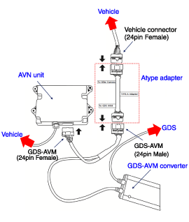
To perform multi-view camera manual footage compensation the
equipment in the figure below must be interconnected with the vehicle. 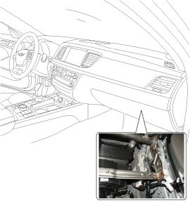
|
| 4. |
The vehicle's ignition (IG) must be turned off. |
| 5. |
The glove box will be removed to connect the connector of the GDS-Multi-view Camera device to the Multi-view Camera Unit.
(Refer to Multi-view Camera System - "Multi-view Camera Unit") |
| 6. |
The wire harness and connecting connector (24 pins) running from the Multi-view Camera unit to the vehicle side will be removed. 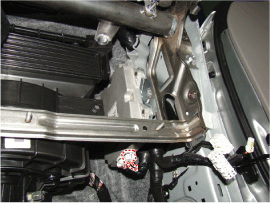
|
| 7. |
The GDS-Multi-view Camera Image Capture equipment connector
(24 pine) will be connected to the place where the Multi-view Camera
unit connector is.
Once connected, a T shape will form as seen in the picture below.
|
When connecting the connector one must be sure to hear a 'click'. |
|
| 8. |
The GDS VCI and vehicle are connected with DLC cable.
|
The VCI and Multi-view Camera should have a secure connection with the PC using a USB cable.
The GDS-VCI must connect to the PC with a USB cable to
transmit compensation image data from the Multi-view Camera electronic
control unit.
With the ignition (IGN) power switched ON, the 24PIN
connectors of the Multi-view Camera electronic control unit (ECU) are
not to be removed. (risk of causing malfunction in the control module) |
|
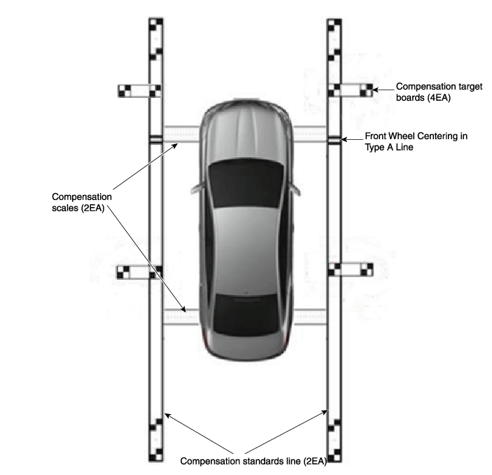
| 9. |
Install around the vehicle by referring to the guide that was
provided along with the compensation scales (2), compensation standard
line boards (2), and compensation target boards (4).
|
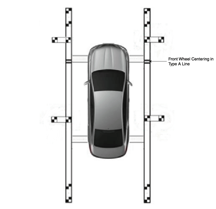
When centering the wheels on the compensation standards line board, the A-type and B-type must be centered separately.
Caution should be taken because the center location of the
white and black compensation plate consist of standard coordinates the
accuracy(distance / right-angles) are very important.
| - |
The front and rear / left and right centering should be maintained within a deviation of 3cm. |
| - |
When centering the vehicle the rotation deviation should be maintained within 1 degree on the side. |
|
|
The GENESIS (DH) and EQUUS (VI) make are models that have the A-type reference line. |
|
| 10. |
Keep the IG on while the car is stopped, confirm the location
of the gear stick is on ‘P’ and engage the parking brake on a flat
area. |
| 11. |
Perform the work with the Multi-view Camera switch in the vehicle set to ‘ON.’ |
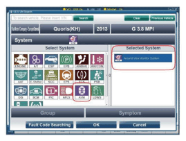
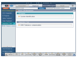
| 12. |
Perform Multi-view Camera manual tolerance compensation according to GDS diagnostics display. 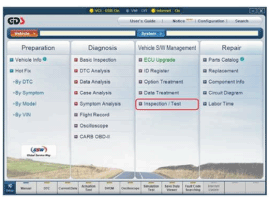
|
| 13. |
The next procedure is to proceed by referring to the GDS
screen instructions and the ‘manual tolerance compensation’ manual
supplied along with the equipment. 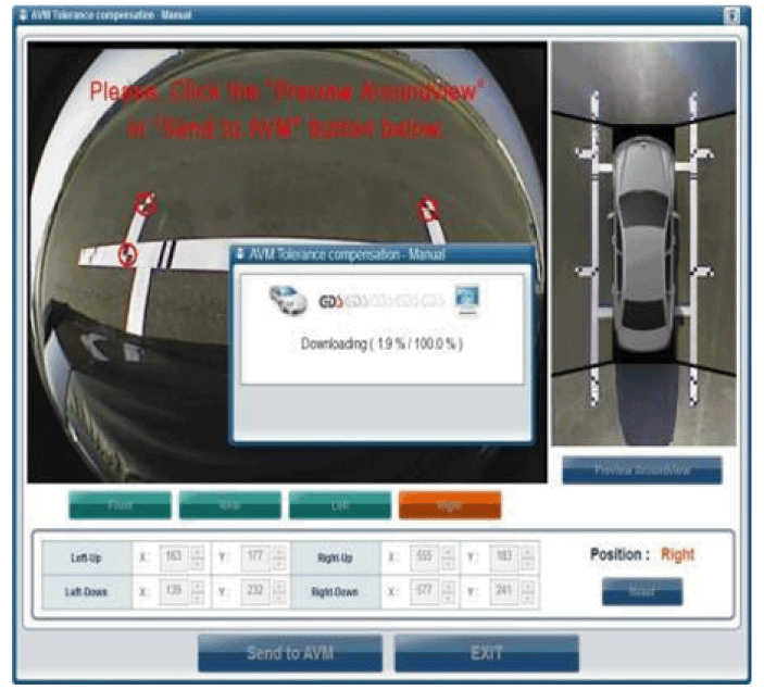
|
Environment that is required to perform compensation task

| 1. |
The white and black compensation panel (SST: 09957-CM100) should be installed with a consideration for the orientation. |
| 2. |
The location accuracy (distance/perpendicularity) is very
important as the center of the white and black compensation panel is the
reference coordinates. |
| 3. |
The floor surface should be painted a matte green to detect
the compensation panel signs automatically and to minimize the light
reflections caused by lighting.
Target
| Color (matte)
| Floor surface
| Green
| Compensation panel
| White/black
| Confirmation line
| White
|
|
| 4. |
The floor surface is green. The compensation target is white and black. The confirmation line is white. |
| 5. |
The lane and compensation panel signs should be free of dirt and there should no signs or patterns except the designated sign. |
| 6. |
The task is sensitive to the impact of external light sources
(sunshine and reflected light from the floor) and it is recommended
that a screen should be placed around the work place (8.5 x 5.2 m). |
| 7. |
Indirect lighting is recommended and a constant illumination should be maintained to minimize sunlight or reflected light. |
| 8. |
The following is the car alignment criteria.
| A. |
The vehicle's front wheel axle must be at the 1 m mark in the work area. (refer to the front wheel axle arrangement location) |
| B. |
The alignment error margin for the front and rear, and left and right should be less than 3 cm. |
| C. |
The margin of rotation error during vehicle alignment must be less than 1 degree left and right. |
|
The recognition procedure for the Multi-view Camera compensation point is sensitive to light reflected off the floor.
The task is sensitive to the impact of external light sources
(sunshine and reflected light from the floor) and it is recommended
that a screen should be placed around the work place (8.5 x 5.2 m).
Carry out compensation in the work place where the floor surface is painted green and there is no glare. |
|
Tolerance Compensation Process
| 1. |
Vehicle's Fixed Position Alignment
Align the target vehicle on to the fixed position
| A. |
The center of the vehicle must be aligned with the center of the work floor |
| B. |
The front wheel of the vehicle must be positioned with the axis alignment position |
|
| 2. |
Preparation
| A. |
Hood/Trunk/Doors closed and Outside Mirror at default position |
| B. |
IGN, ON & Shift Lever at ‘N’ Position |
| C. |
Multi-view Camera Switch ‘ON’ |
| D. |
Do not install the exhaust intake pipe to eliminate any interference on the rear camera. |
| E. |
The exhaust gas fume during winter may affect the rear camera compensation process so do not turn ON the engine |
|
| 3. |
Check normal operation
Check that Multi-view operates without error
| A. |
Select Front + Multi-view Mode on the Head Unit Screen |
|
| 4. |
Start Tolerance Compensation
Start the compensation task by using the GDS (scan tool)
| A. |
The Multi-view Camera Switch indicator blinks before compensation task is complete |
| B. |
DTC is generated and saved if compensation is not performed or failed |
|
| 5. |
Determining Tolerance Compensation Limit Specification
| A. |
Select Front View Mode (refer to below illustration) |
| B. |
Switch to the Front Camera Compensation Point Input Screen |
| C. |
Check if the blinking ‘+’ indicator is within the upper left/right compensation board |
|
| 6. |
Performing Tolerance Compensation
Front > Rear > Left > Right Camera ; The compensation point input screen switches in that order
| (1) |
Input the center of the upper left compensation point [M1] with Stylus Pen 
|
| (2) |
Check the recognition result display of the two upper left points [P1, P2] 
|
Click on the "Retry" button in case of incorrect input and start from beginning. |
|
| (3) |
Input the center of the upper right compensation point [M2] with Stylus Pen. 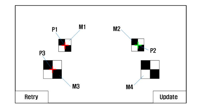
|
| (4) |
Check the recognition result display of the two upper right points [P2, P4]. 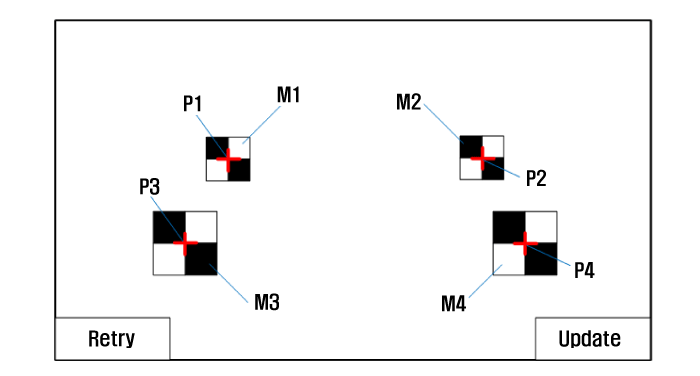
|
Click on the "Retry" button in case of incorrect input and start from beginning. |
|
| (6) |
Switch to the Rear Camera Compensation Point Input Screen |
| (7) |
Repeat on rear, left, and right cameras |
|
| 7. |
End Tolerance Compensation
| (1) |
Click on the "Complete" button after completing the compensation for 4 cameras
|
Do not operate the IGN. Key/ Shift Lever N Position/ Multi-view Camera Switch until the task is complete. |
|
| (2) |
Automatically compute date save reset Compensated Result is displayed as the initial screen.
|
Approximately 90 seconds from auto reset until video is displayed. |
|
| (3) |
If the Multi-view video is displayed properly, then end the
tolerance compensation process. You can now start the engine and move
the vehicle. |
|
| 8. |
Tolerance Compensation Task Check Procedure
| (1) |
Check if the Multi-view Camera default setting video is
displayed. (If the shift lever is at N and Multi-view Camera_SW ON, the
display shows Front View Screen + Multi-view Screen) |
| (2) |
Check if the refreshed screen displays the Multi-view video. |
| (3) |
Visually check that the white line in the Multi-view video is
displayed straight as shown in below image. Up to 8cm deviation is
allowed, and if margin of error is within 8cm, then the system is
determined to be in normal operation. |
| (4) |
If the Multi-view video is not displayed correctly, then the compensation task must be repeated. |
| (5) |
If the tolerance compensation is completed properly, then the vehicle power is switched to OFF mode. |
|
Diagnosis
| 1. |
Check Output Video on the Multi-view Camera Head Unit Screen
If the video is not displayed normally in the Multi-view
Camera Video Check Phase, then perform below check list and check the
video again.
| (1) |
Are the connector for each camera properly connectedx |
| (2) |
Is there any obstacles in the camera's view anglex |
| (3) |
Is the Multi-view Camera ECM operating properlyx |
|
| 2. |
In case Tolerance Compensation Mode cannot be entered
| (1) |
Is the shift lever position at ‘N’ rangex |
| (2) |
Is the vehicle parkedx |
| (3) |
Is the GDS in Tolerance Compensation Modex |
|
| 3. |
In case Compensation Point is not recognized
If the compensation point is incorrectly recognized or not
recognized at all at the Compensation Point Recognition Phase, then
perform below check list and reinput the compensation point.
| (1) |
Check that work area is not exposed to the sun light. |
| (2) |
Check that the work area is not exposed to other vehicle's head lamp or other source of light. |
| (3) |
Check if there is reflection of light on the compensation board and the AVN cannot recognize the Compensation Board Indication. |
| (4) |
Check that there is no other object on the Compensation Board. |
| (5) |
Check that there is no debris on the camera lens, or that the
Compensation Board indication is difficult to recognize due to lens
protection film. |
| (6) |
Check that there is no other object adjacent to the
Compensation Board Indication, which may also create a shadow on the
Compensation Board Indication. |
| (7) |
Check that there is no obstacle blocking the camera view while performing compensation task.
|
The recognition procedure for the Multi-view Camera compensation point is sensitive to light reflected off the floor.
The task is sensitive to the impact of external light sources
(sunshine and reflected light from the floor) and it is recommended
that a screen should be placed around the work place (8.5 x 5.2 m).
Carry out compensation in the work place where the floor surface is painted green and there is no glare. |
|
|
Circuit Diagram
Multi-view Camera System Input/Output
1.
Camera input
ItemSpecificationLens angle of view190 degreesAngle of viewHorizontal186 degreesVertical135 degreesFunctionProvides ...
 Hyundai Equus: Repair procedures


 Schematic Diagrams
 Multi-view Camera Unit Components and Components Location


