 Hyundai Equus: Relay Box (Passenger Compartment) Repair procedures
Second generation VI (2009–2026) / Hyundai Equus VI 2009-2026 Service Manual / Body Electrical System / Fuses And Relays / Relay Box (Passenger Compartment) Repair procedures
Second generation VI (2009–2026) / Hyundai Equus VI 2009-2026 Service Manual / Body Electrical System / Fuses And Relays / Relay Box (Passenger Compartment) Repair procedures
| Inspection |
| 1. |
The SJB can be diagnosed by using the GDS. The SJB
communicates with the GDS which then displays inputs and outputs along
with codes. |
| 2. |
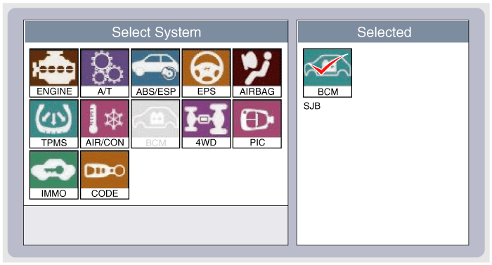
To diagnose the SJB function, select the vehicle model, BCM and SJB.
|
| 3. |
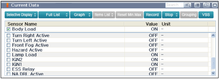
To consult the present input/out value of SJB, "Current DATA". It provides information of SJB input/output conditions.
|
| 4. |
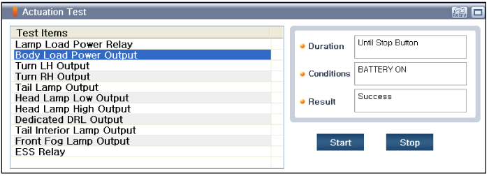
To perform functional test on SJB outputs, select "Actuation Test"
|
| Removal |
Samrt Junction Box (SJB)
| 1. |
Disconnect the negative (-) battery terminal. |
| 2. |
Remove the crash pad lower panel.
(Refer to Body - "Crash Pad Lower Panel") |
| 3. |
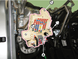
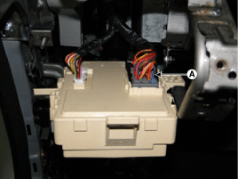
Disconnect the smart junction box (SJB) connectors and nuts.
|
| 4. |
Disconnect the connector (A) in the back side of the smart junction box.
|
| Installation |
| 1. |
Connect the connectors and receiver antenna cable on the smart junction box. |
| 2. |
Install the smart junction box module. |
| 3. |
Install the crash pad lower panel. |
| 4. |
Connect the negative (-) battery terminal. |
 Relay Box (Passenger Compartment) Description and Operation
Description
1.
Smart Junction Box(SJB)
(1)
General function : Interior Junction Box + some functions of BCM
(2)
It controls loads with CAN communication and IPS.
(3)
IPS stands for Intel ...
See also:
VSM OFF Switch Repair procedures
Removal
1.
Disconnect the negative (-) battery terminal.
2.
Remove the airbag module.
(Refer to Restraint - "Driver Airbag (DAB) Module and Clock Spring")
3.
Remove the TORX screws to rem ...
Components and Components Location
Components
1. LDWS ON/OFF Switch2. Instrument Cluster3. LDWS Unit4. Camera Module
...
Radiator Grill Components and Components Location
Component Location
1. Radiator grill
...
Categories
Hyundai Equus Manuals
© 2011-2026 Copyright www.heqmanual.com

