
 Hyundai Equus: Pre-active Seat Belt (PSB) Repair procedures
Second generation VI (2009–2026) / Hyundai Equus VI 2009-2026 Service Manual / Restraint / Seat Belt Pretensioner / Pre-active Seat Belt (PSB) Repair procedures
Hyundai Equus: Pre-active Seat Belt (PSB) Repair procedures
Second generation VI (2009–2026) / Hyundai Equus VI 2009-2026 Service Manual / Restraint / Seat Belt Pretensioner / Pre-active Seat Belt (PSB) Repair procedures
Second generation VI (2009–2026) / Hyundai Equus VI 2009-2026 Service Manual / Restraint / Seat Belt Pretensioner / Pre-active Seat Belt (PSB) Repair procedures
| Removal |
| 1. |
Disconnect the battery negative cable, and wait for at least three minutes before beginning work. |
| 2. |
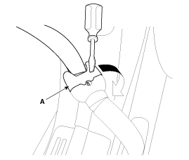
Remove the safety belt (A) by turning it in the direction of arrow using a flat-head screwdriver.
|
| 3. |
Remove the center pillar lower trim.
(Refer to Body - "Center Pillar Trim") |
| 4. |
Remove the center pillar upper trim.
(Refer to Body - "Center Pillar Trim") |
| 5. |
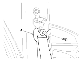
After loosening the mounting bolt, then remove the front seat belt lower anchor (A).
|
| 6. |
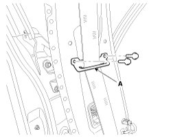
Loosen the front seat belt webbing guide (A) mounting bolts.
|
| 7. |
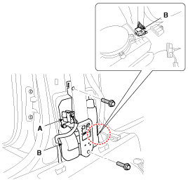
After disconnecting the pretensioner connector lock pin,
remove the front seat belt pretensioner connectors (A), loosen the
mounting bolts, then remove the front seat belt pretensioner (B).
|
| Installation |
| 1. |
Turn the ignition switch OFF. |
| 2. |
Disconnect the battery negative cable and wait for at least three minutes. |
| 3. |
Install in the reverse order of removal. |
| 4. |
Reconnect the battery negative cable. |
| 5. |
After installing the seat belt pretensioner, confirm proper system operation:
Turn the ignition switch ON; the SRS indicator light should turn on for about six seconds and then go off. |
| PSB Variant Coding |
When replacing a PSB of the driver’s or passenger’s seat
with a new one, be sure to carry out the Variant Coding procedure using
GDS. (Only for vehicles without SCC)
PSB variants are coded for vehicles equipped with SCC.
Therefore, Variant Coding should be performed only for vehicles without
SCC. |

PSB Variant Coding
| 1. |
Turn the ignition switch OFF. |
| 2. |
Connect the GDS. |
| 3. |
Turn the ignition switch ON without the engine running. |
| 4. |
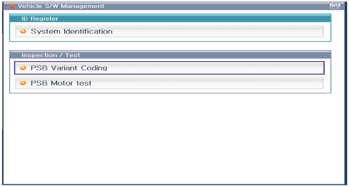
Select "PSB-LH" or "PSB-RH", and then select "PSB Variant Coding".
|
| 5. |
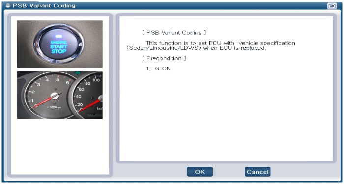
Follow the instructions on the screen, and then press the "OK" button.
|
| 6. |
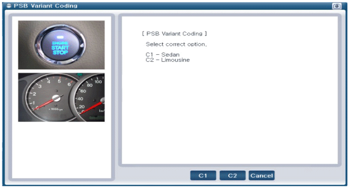
Click "C1" if the vehicle is sedan type.
Click "C2" if the vehicle is limousine type.
|
| 7. |
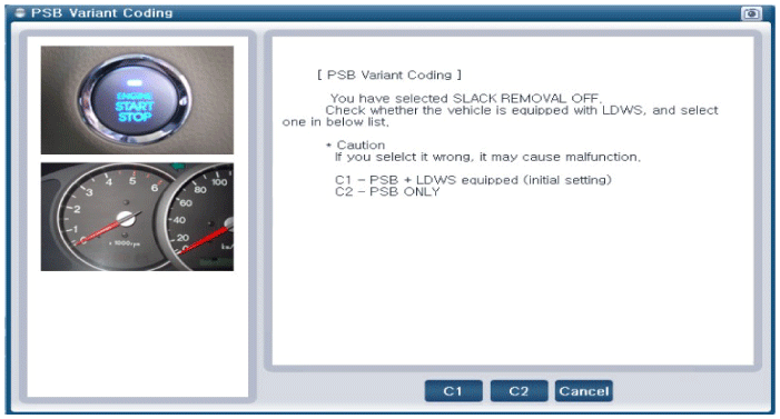
Click "C1" for vehicles with LDWS.
Click "C2" for vehicles without LDWS.
|
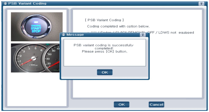
| 8. |
Select the "OK" button after the "Complete" message has appeared.
|
 Pre-active Seat Belt (PSB) Schematic Diagrams
Circuit Diagram
...
 Brake System
...
See also:
Components and Components Location
Components
...
Front Strut Assembly Repair procedures
Removal
1.
Remove the front wheel and tire (A) from front hub .
Tightening torque:
88.3 ~ 107.9 N.m (9.0 ~ 11.0 kgf.m, 65.1 ~ 79.6 lb-ft)
•
Be careful not to dama ...
Specifications
Specification
Air Conditioner
ItemSpecificationCompressorType7VSX18Oil type & CapacityPAG 120± 10cc (4.1±0.3oz.)Pulley typeAround rubber damperDisplacement180cc/revCondenserHeat rejection18, ...
Categories
Hyundai Equus Manuals

© 2011-2026 Copyright www.heqmanual.com