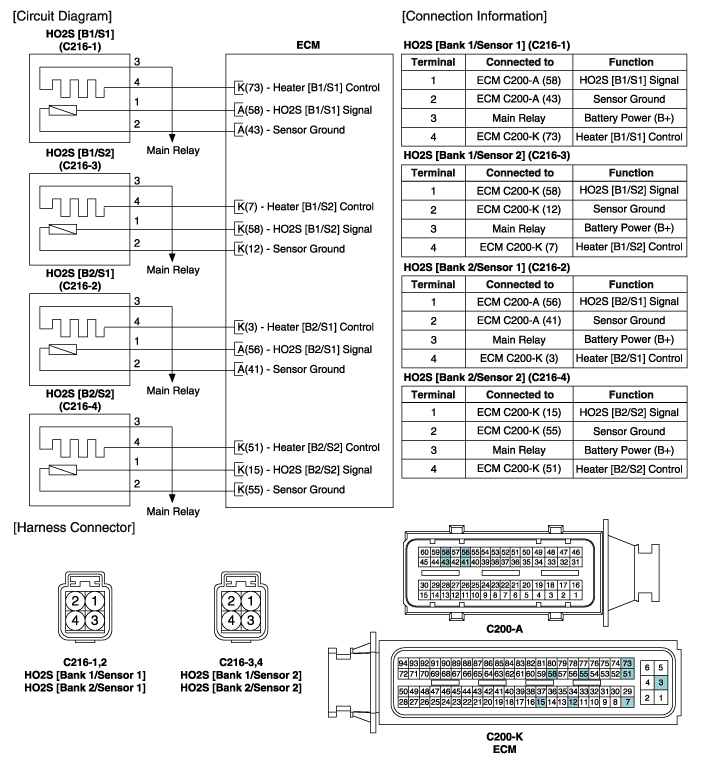
 Hyundai Equus: Heated Oxygen Sensor (HO2S) Schematic Diagrams
Second generation VI (2009–2026) / Hyundai Equus VI 2009-2026 Service Manual / Engine Control/Fuel System / Engine Control System / Heated Oxygen Sensor (HO2S) Schematic Diagrams
Second generation VI (2009–2026) / Hyundai Equus VI 2009-2026 Service Manual / Engine Control/Fuel System / Engine Control System / Heated Oxygen Sensor (HO2S) Schematic Diagrams
| Circuit Diagram |

 Heated Oxygen Sensor (HO2S) Troubleshooting
Signal Waveform
Fig.1) The signal waveforms of front HO2S(the upper) and heater(the lower) at idle
Fig.2) The signal waveforms of rear HO2S(the upper) and heater(the lower) at idle
Fig.3) Typical ...
 Heated Oxygen Sensor (HO2S) Repair procedures
Inspection
1.
Turn the ignition switch OFF.
2.
Disconnect the HO2S connector.
3.
Measure resistance between the HO2S terminals 3 and 4.
4.
Check that the resistance is within the speci ...
See also:
Auto Defogging Sensor Repair procedures
Inspection
To inspect and diagnose the sensor, refer to Self-Diagnosis procedure and DTC guide.
Replacement
1.
Disconnect the negative (-) battery terminal.
2.
Using a screwdriver or remov ...
Operating HomeLink®
To operate, simply press and release the programmed HomeLink® button. Activation
will now occur for the trained device (i.e. garage door opener, gate operator, security
system, entry door lock, h ...
Checking the coolant level
WARNING Removing radiator cap
Never attempt to remove the radiator cap while the engine is operating
or hot. Doing so might lead to cooling system and engine damage and could result
in ser ...
Categories
Hyundai Equus Manuals
© 2011-2026 Copyright www.heqmanual.com
