
 Hyundai Equus: 27 Brake Control Solenoid Valve Schematic Diagrams
Second generation VI (2009–2026) / Hyundai Equus VI 2009-2026 Service Manual / Automatic Transmission System (SBC) / Automatic Transmission Control System / 27 Brake Control Solenoid Valve Schematic Diagrams
Second generation VI (2009–2026) / Hyundai Equus VI 2009-2026 Service Manual / Automatic Transmission System (SBC) / Automatic Transmission Control System / 27 Brake Control Solenoid Valve Schematic Diagrams
| Circuit Diagram |
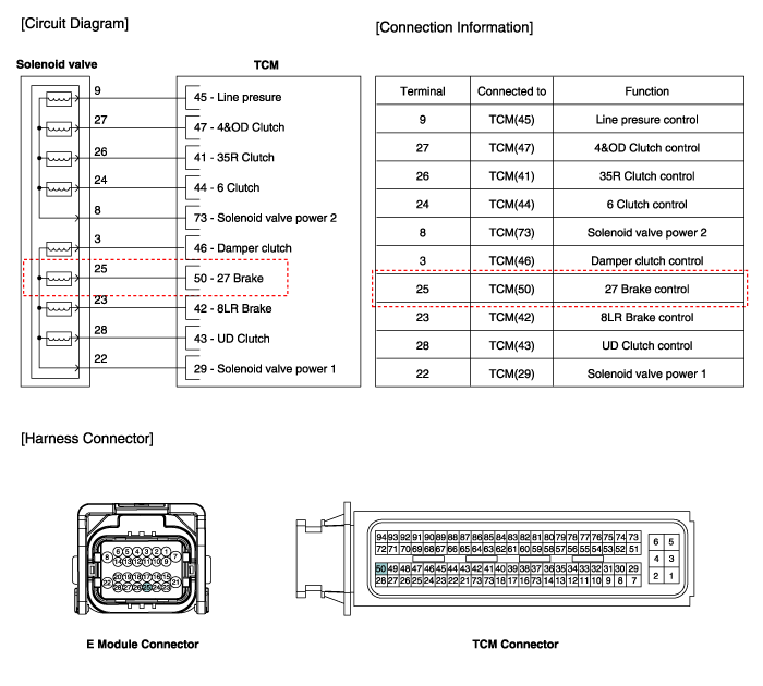
 27 Brake Control Solenoid Valve Specifications
Specifications
Direct control VFS[27/B]
x Control type : Normal low type
Control Pressure kpa (kgf/cmx, psi)0~1569.06 (0~16,0~227.57)Current value(mA)0~1100 Internal resistance ...
 27 Brake Control Solenoid Valve Repair procedures
Inspection
1.
Turn ignition switch OFF.
2.
Disconnect the E Module connector.
3.
Measure resistance between sensor signal terminal and sensor ground terminal.
4.
Check that the res ...
See also:
Rear Variable Damper Schematic Diagrams
Circuit Diagram
1.
Rear variable damper connector
2.
Rear variable damper terminal function
TerminalFunction1Variable damper (-)2Variable damper (+)
3.
Circuit diagram ...
Description and Operation
OBD-II review
1. Overview
The California Air Resources Board (CARB) began regulation of
On Board Diagnostics (OBD) for vehicles sold in california beginning
with the 1988 model year. The first ...
Main Crash Pad Assembly Repair procedures
Replacement
•
Put on gloves to protect your hands.
•
When prying with a flat-tip screwdriver, wrap it with
protective tape, and apply p ...
Categories
Hyundai Equus Manuals

© 2011-2026 Copyright www.heqmanual.com