 Hyundai Equus: Body Control Module (BCM) Repair procedures
Second generation VI (2009–2026) / Hyundai Equus VI 2009-2026 Service Manual / Body Electrical System / BCM (Body Control Module) / Body Control Module (BCM) Repair procedures
Second generation VI (2009–2026) / Hyundai Equus VI 2009-2026 Service Manual / Body Electrical System / BCM (Body Control Module) / Body Control Module (BCM) Repair procedures
| Removal |
| 1. |
Disconnect the negative (-) battery terminal. |
| 2. |
Remove the crash pad lower panel after loosening the mounting screws.
(Refer to Body - "Crash Pad Lower Panel") |
| 3. |
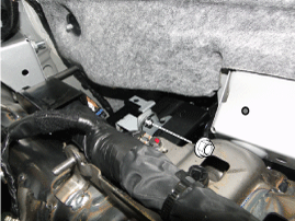
Disconnect the connector, bolt and nuts from smart key unit, BCM and tilt & telescopic unit.
|
| 4. |
Remove the smart key (A) and BCM unit (B) after loosening bolt and nuts.
|
| Installation |
| 1. |
Install the smart key unit and BCM unit and then connect the connectors. |
| 2. |
Install the crash pad lower panel. |
| 3. |
Connect the negative (-) battery terminal. |
| Inspection |
| 1. |
The body control module can diagnose by using the GDS more quickly.
The BCM communicates with the GDS and then reads the input/output value and drives the actuator. |
| 2. |
To diagnose the BCM function, select the menu of model and body control module.
|
| 3. |
Select "Input/output monitoring", if you will check current
data of body network system. It provides input/output status of each
module.
|
| 4. |
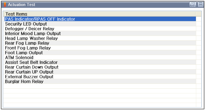
If you will check each module data operation forcefully, select "Actuation test".
|
| 5. |
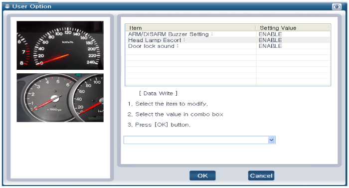
If you want to change user option, select “user option”.
|
 Description and Operation
Description
Communication Network Diagram
AbbreviationExplanationC_CANChassis Controller Area NetworkB_CANBody Controller Area NetworkMM_CANMulti media Controller Area NetworkSMKSmart Key UnitDD ...
See also:
Fuel Pressure Sensor (FPS) Troubleshooting
Fail-Safe Mode
ItemFail-SafeDuty (%)85
If the fuel pressure sensor malfunctions, it enters fail safe
mode. This means that the fuel pressure rises to match the increasi ...
Gate operator & Canadian programming
During programming, your handheld transmitter may automatically stop transmitting.
Continue to press the Integrated HomeLink® Wireless Control System button (note
steps 2 through 4 in the Standar ...
Pre-active Seat Belt (PSB) Components and Components Location
Components
Main Function
1.
Full Retraction
Maintains a more safe posture by strongly rewinding the seat belt right before a crash.
[Operation Condition]
A.
When a frontal crash is detected b ...
Categories
Hyundai Equus Manuals
� 2011-2026 Copyright www.heqmanual.com


