 Hyundai Equus: Sunroof Motor Repair procedures
Second generation VI (2009–2026) / Hyundai Equus VI 2009-2026 Service Manual / Body Electrical System / Sun Roof / Sunroof Motor Repair procedures
Hyundai Equus: Sunroof Motor Repair procedures
Second generation VI (2009–2026) / Hyundai Equus VI 2009-2026 Service Manual / Body Electrical System / Sun Roof / Sunroof Motor Repair procedures
Second generation VI (2009–2026) / Hyundai Equus VI 2009-2026 Service Manual / Body Electrical System / Sun Roof / Sunroof Motor Repair procedures
| Replacement |
| 1. |
Disconnect the negative (-) battery terminal. |
| 2. |
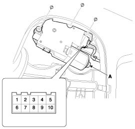
Remove the overhead console then remove the sun roof motor
mounting screws (3EA). And then remove the sunroof motor (A) after
disconnecting the connector (10 Pin).
|
| 3. |
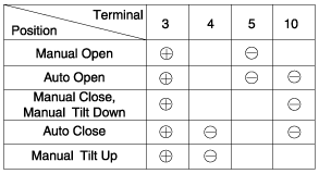
Ground the terminals as below table, and check that the sunroof unit operates as below table.
|
| 4. |
Make these input tests at the connector
if any test indicates a problem, find and correct the cause, then recheck the system.
If all the input tests prove OK, the sunroof motor must be faulty; replace it.
|
Resetting The Sunroof
Whenever the vehicle battery is disconnected or discharged,
or you use the emergency handle to operate the sunroof, you have to
reset your sunroof system as follows :
| 1. |
Turn the ignition key to the ON position. |
| 2. |
According to the position of the sunroof, do as follows.
|
| 3. |
Release the TILT button. |
| 4. |
Press and hold the TILT button once again until the sunroof
has returned to the original position of TILT after it is raised a
little higher than the maximum TILT position.
When this is complete, the sunroof system is reset. |
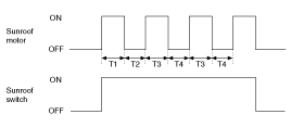
Protecting The Overheated Motor
In order to protect the overheated sunroof motor by
continuous motor operation, the sunroof ECU controls the Run-time and
Cool-time of motor as followings;
| 1. |
The Sunroof ECU detects the Run- time of motor |
| 2. |
Motor can be operated continuously for the 1st Run-time(120 ± 10sec.). |
| 3. |
Motor which is operated continuously stops operating after the 1st Run-time(120 ± 10sec.). |
| 4. |
And then Motor is not operated for the 1st Cool-time(18 ± 2sec.). |
| 5. |
Motor is operated for the 2nd Run-time(10 ± 2sec.) at the continued motor operation after 1st Cool-time(18 ± 2sec.) |
| 6. |
Motor which is operated continuously stops operating after the 2nd Run-time(10 ± 2sec.) |
| 7. |
Motor is not operated for the 2nd Cool-time(18 ± 2sec.). |
| 8. |
Motor repeats the 2nd Run-time and 2nd Cool-time at the continued motor operation.
T1 : 120 ± 10 sec., T2 : 18 ± 2 sec.,
T3 : 10 ± 2 sec., T4 : 18 ± 2 sec. |
 Sunroof Switch Repair procedures
Inspection
1.
Disconnect the negative (-) battery terminal.
2.
Open the sunglass case cover from the overhead console then
remove the 2 screws holding the overhead console. Disconnect the sw ...
 Lighting System
...
See also:
Steering Column Shroud Panel Components and Components Location
Component Location
1. Steering column shroud lower panel2. Steering column shroud upper panel
...
Cleaning the interior window glass
If the interior glass surfaces of the vehicle become fogged (that is, covered
with an oily, greasy or waxy film), they should be cleaned with glass cleaner. Follow
the directions on the glass clea ...
Child-Protector Rear Door Locks
The child safety lock is provided to help prevent children seated in the rear
from accidentally opening the rear doors. The rear door safety locks should be used
whenever children are in the v ...
Categories
Hyundai Equus Manuals

© 2011-2026 Copyright www.heqmanual.com