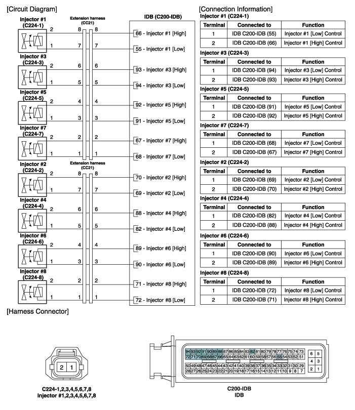
 Hyundai Equus: Injector Schematic Diagrams
Second generation VI (2009–2026) / Hyundai Equus VI 2009-2026 Service Manual / Engine Control/Fuel System / Engine Control System / Injector Schematic Diagrams
Second generation VI (2009–2026) / Hyundai Equus VI 2009-2026 Service Manual / Engine Control/Fuel System / Engine Control System / Injector Schematic Diagrams
| Circuit Diagram |

 Injector Troubleshooting
Signal Waveform
...
 Injector Repair procedures
Inspection
1.
Turn the ignition switch OFF.
2.
Disconnect the injector connector.
3.
Measure resistance between the injector terminals 1 and 2.
4.
Check that the resistance is within t ...
See also:
Cowl Cross Bar Assembly Repair procedures
Replacement
•
Put on gloves to protect your hands.
•
When prying with a flat-tip screwdriver, wrap it with
protective tape, and apply p ...
Rain Sensor Description and Operation
Description
Integrated Rain Sensor
Integrated rain sensor (A) controls three systems: front wiper, auto-light, and central air conditioner.
1.
Wiper Control System
When "AUTO" switch signal i ...
Power Trunk (if equipped)
(1) Power Trunk Main Control button
(2) Power Trunk Open button
(3) Power Trunk Close button
(4) Power Trunk Lock button
To open:
1. Make sure the shift lever is in P(Park).
2. Then do one o ...
Categories
Hyundai Equus Manuals
© 2011-2026 Copyright www.heqmanual.com
