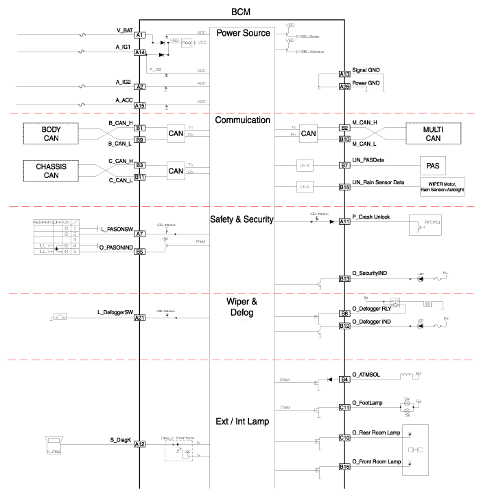
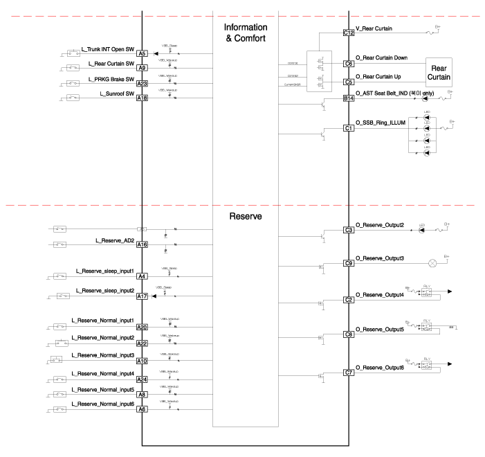
 Hyundai Equus: Schematic Diagrams
Second generation VI (2009–2024) / Hyundai Equus VI 2009-2024 Service Manual / Body Electrical System / BCM (Body Control Module) / Schematic Diagrams
Second generation VI (2009–2024) / Hyundai Equus VI 2009-2024 Service Manual / Body Electrical System / BCM (Body Control Module) / Schematic Diagrams
| Circuit Diagram |


 Components and Components Location
Components Location
1. Smart Junction Box (SJB)2 . Body Control Module (BCM)3 . Smart Key Unit (SMK)4 . Driver Door Module (DDM)5 . Assis Door Module (ADM)6 . Cluster (CLU)7 . Around View Monitor ...
 Description and Operation
Description
Communication Network Diagram
AbbreviationExplanationC_CANChassis Controller Area NetworkB_CANBody Controller Area NetworkMM_CANMulti media Controller Area NetworkSMKSmart Key UnitDD ...
See also:
Blade inspection
✽ NOTICE
Commercial hot waxes applied by automatic car washes have been known to make
the windshield difficult to clean.
Contamination of either the windshield or the wiper blades with ...
A/C Pressure Transducer Description and Operation
Description
The A/C Pressure Transducer (APT) converts the pressure value
of high pressure line into voltage value after measuring it. By
converted voltage value, engine ECU controls the coolin ...
Battery Repair procedures
Removal
1.
Disconnect the battery sensor connector (A), battery nagative terminal (B) and positive terminal (C).
2.
Disconnect the vent hose connector (A) from the battery air vent hole.
3. ...
Categories
Hyundai Equus Manuals
© 2011-2024 Copyright www.heqmanual.com
