 Hyundai Equus: Reservoir Tank Repair procedures
Second generation VI (2009Ц2024) / Hyundai Equus VI 2009-2024 Service Manual / Suspension System / Air Suspension System / Reservoir Tank Repair procedures
Second generation VI (2009Ц2024) / Hyundai Equus VI 2009-2024 Service Manual / Suspension System / Air Suspension System / Reservoir Tank Repair procedures
| Removal |
|
| 1. |
Removal the front bumper.
(Refer to Body - "Front bumper") |
| 2. |
Removal the left head amp.
(Refer to Body Electrical System - "Head lamp leveling device") |
| 3. |
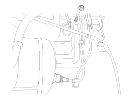
Removal the nut & clip & air hose.
|
| 4. |
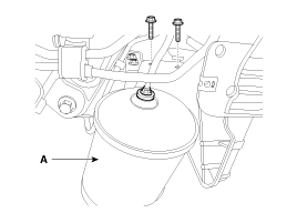
Disconnect the reservoir tank (A) by remove the bolt & air tube.
|
| Installation |
| 1. |
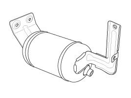
Install the reservoir tank (A).
|
| 2. |
Install the nut & clip & air hose.
|
Air filling
| System air filling machine |
System air filling is done at the factory before delivering
the vehicle. In case of workshop, it should be done after replacing the
related parts or the system air was drained because of other repairing
works. Follow the recommended procedure for system air filling.
| 1. |
Prepare the compressed air (12bar) using the air filling machine. |
| 2. |
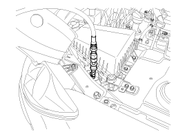
Connect the air outlet nozzle in the machine to the air filling valve (RH side of engine room) in the vehicle. |
| 3. |
Ignition ON (engine off) and connect the scanner. |
| 4. |
Lift up the vehicle. (all wheels must be rebounded) |
| 5. |
Opening the lever in the machine, starts to fill the air from
filling machine to the reservoir tank in the vehicle until the whistle
sound stops. |
| 6. |
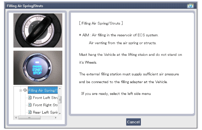
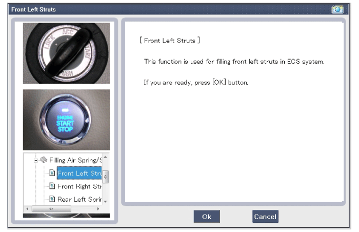
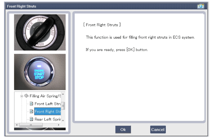
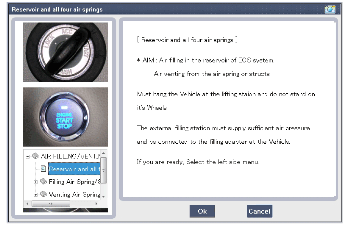
Enter the menu of system air filling in the scanner and follow the instruction in the scanner.
The compressed air will be transferred to the front air
spring and rear air spring accordingly by operating the compressor and
solenoid valves. |
| 7. |
Take down the vehicle after completing the air filling.
|
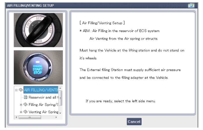
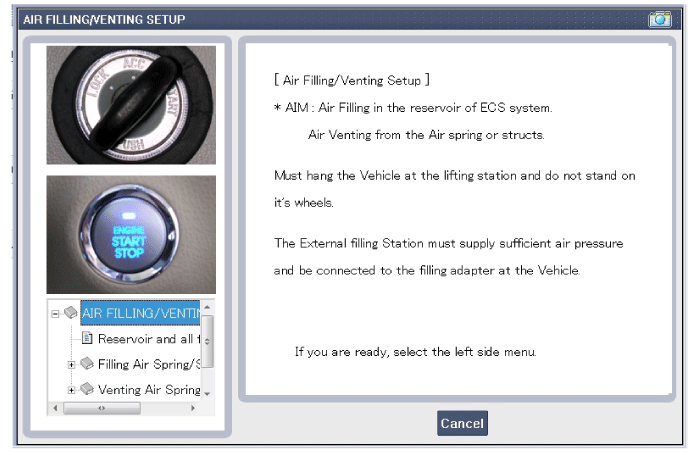
Air Filling/Venting Setup
| 1. |
Connect to the GDS diagnostic.
|
 Reservoir Tank Description and Operation
Description
The volume is 5.2 liter and the maximum operation pressure is 16bar. (Bursting pressure: 40bar)
The pressure of reservoir tank is monitored every 30 min while driving. ...
 ECU Components and Components Location
Components Location
1. ECU2. ECU bracket3. ECU support
...
See also:
Components and Components Location
Components
[Front Console]
1. Floor console assembly2. Front console upper complete 3. Console side cover [LH]4. Console side cover [RH]5. Console center mounting bracket6. Console rear mounti ...
Adaptive Front Lighting System Description and Operation
Description
AFLS Unit(ECU)
AFLS located in Cockpit Module is provided information of vehicle (steering wheel signal,vehicle speed, inclination of vehicle).
Based on provided information , it calc ...
Rear Driveshaft (VL-VL TYPE) Components and Components Location
Component location
1. Rear driveshaft assembly(R)2. Rear driveshaft assembly(L)
...
Categories
Hyundai Equus Manuals
© 2011-2024 Copyright www.heqmanual.com


