
 Hyundai Equus: Rear Driveshaft (VL-VL TYPE) Repair procedures
Second generation VI (2009–2026) / Hyundai Equus VI 2009-2026 Service Manual / Driveshaft and axle / Rear Driveshaft Assembly / Rear Driveshaft (VL-VL TYPE) Repair procedures
Hyundai Equus: Rear Driveshaft (VL-VL TYPE) Repair procedures
Second generation VI (2009–2026) / Hyundai Equus VI 2009-2026 Service Manual / Driveshaft and axle / Rear Driveshaft Assembly / Rear Driveshaft (VL-VL TYPE) Repair procedures
Second generation VI (2009–2026) / Hyundai Equus VI 2009-2026 Service Manual / Driveshaft and axle / Rear Driveshaft Assembly / Rear Driveshaft (VL-VL TYPE) Repair procedures
| Replacement |
| 1. |
Loosen the wheel nuts slightly.
Raise the vehicle, and make sure it is securely supported. |
| 2. |
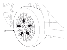
Remove the rear wheel and tire (A) from rear hub.
|

| 3. |
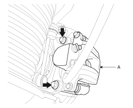
Remove the brake caliper mounting bolts and then hold the brake caliper assembly (A) with wire as shown in the illustration.
|
| 4. |
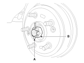
Remove the split pin (A) then remove castle nut (B) and washer from the front hub under applying the brake.
|
| 5. |
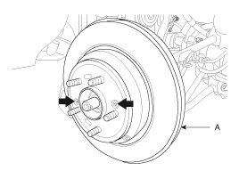
Remove the rear brake disc (A).
|
| 6. |
Disconnect the parking brake cable (A).
|
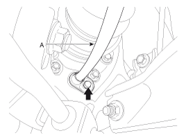
| 7. |
Remove the wheel speed sensor (A) from the rear axle carrier.
|
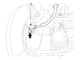
| 8. |
Remove the trailing arm (B) from the rear axle carrier.
|
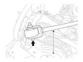
| 9. |
Remove the assist arm (B) from the rear axle carrier.
|
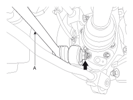
| 10. |
Remove the shock absorber mounting bolt (A).
|
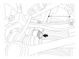
| 11. |
Loosen the front upper arm & rear upper arm link mount
bolts and then remove the front upper arm (A) & rear upper arm (B)
link.
|
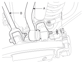
| 12. |
Remove lower arm mount bolt (A) from rear axle carrier.
|
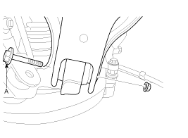
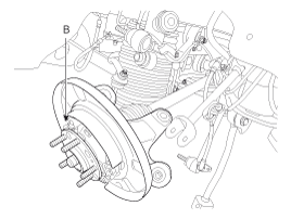
| 13. |
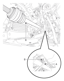
Insert a pry bar (A) between the differential case and joint case, and separate the driveshaft (B) from the differential case.
|
| 14. |
Installation is the reverse order of removal. |
| Inspection |
| 1. |
Check the driveshaft boots for damage and deterioration. |
| 2. |
Check the ball joint for wear and damage. |
| 3. |
Check the splines for wear and damage. |
| 4. |
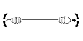
Check the dynamic damper for cracks, wear and position.
|
| 5. |
Check the driveshaft for cracks and wears. |
 Rear Driveshaft (VL-VL TYPE) Components and Components Location
Component location
1. Rear driveshaft assembly(R)2. Rear driveshaft assembly(L)
...

See also:
4&OD Clutch Control Solenoid Valve Schematic Diagrams
Circuit Diagram
...
Front Seat Belt Buckle Components and Components Location
Component Location
1. Front seat belt buckle
...
Purge Control Solenoid Valve (PCSV) Description and Operation
Description
Purge Control Solenoid Valve (PCSV) is installed on the surge
tank and controls the passage between the canister and the intake
manifold. It is a solenoid valve and is open when the ...
Categories
Hyundai Equus Manuals

© 2011-2026 Copyright www.heqmanual.com