
 Hyundai Equus: Heater Control Unit Components and Components Location
Second generation VI (2009–2026) / Hyundai Equus VI 2009-2026 Service Manual / Heating, Ventilation and Air Conditioning / Controller / Heater Control Unit Components and Components Location
Hyundai Equus: Heater Control Unit Components and Components Location
Second generation VI (2009–2026) / Hyundai Equus VI 2009-2026 Service Manual / Heating, Ventilation and Air Conditioning / Controller / Heater Control Unit Components and Components Location
Second generation VI (2009–2026) / Hyundai Equus VI 2009-2026 Service Manual / Heating, Ventilation and Air Conditioning / Controller / Heater Control Unit Components and Components Location
| Control Panel |
| Component |
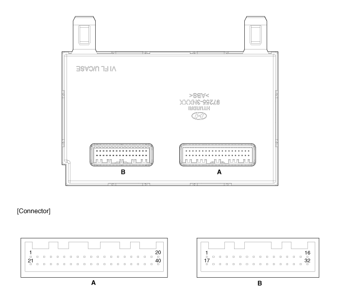
| Connector Pin Function |
| Pin No. | Connector A | Connector B |
| 1 | Ground | Ignition 2 |
| 2 | - | FET (Gate) |
| 3 | Mode Control Actuator (Vent) | FET (Drain Feedback) |
| 4 | Mode Control Actuator (Defrost) | Sensor REF (+5V) |
| 5 | Intake Actuator (Fresh Air) | - |
| 6 | Intake Actuator (Recerculated Air) | - |
| 7 | Driver's Temperature Control Actuator (Cool) | Incar Sensor Motor (-) |
| 8 | Driver's Temperature Control Actuator (Warm) | - |
| 9 | Passenger Temperature Control Actuator (Cool) | - |
| 10 | Passenger Temperature Control Actuator (Warm) | ECV (+) |
| 11 | Auto Defogging Actuator (Open) | ECV (-) |
| 12 | Auto Defogging Actuator (Close) | - |
| 13 | Console Temperature Control Actuator (Cool) | Rear Auto Indcicator |
| 14 | Console Temperature Control Actuator (Warm) | ION Signal |
| 15 | Console Temperature Control Actuator A (Cool) | Blower Motor (+) |
| 16 | Console Temperature Control Actuator A (Warm) | CLEAN Signal |
| 17 | Console Duct Actuator (Vent) | - |
| 18 | Console Duct Actuator (Floor) | - |
| 19 | - | C-Line (Rear Armrest) |
| 20 | Sensor Ground | - |
| 21 | - | C_CAN (High) |
| 22 | Mode Control Actuator Feedback | C_CAN (Low) |
| 23 | Intake Actuator Feedback | - |
| 24 | Driver's Temperature Control Actuator Feedback | Climate_CAN High |
| 25 | Passenger's Temperature Control Actuator Feedback | Climate_CAN Low |
| 26 | Auto Defogging Actuator Feedback | - |
| 27 | Console Temperature Control Actuator Feedback | - |
| 28 | Console Temperature Control Actuator A Feedback | C-Line (Console LCD Panel) |
| 29 | Console Duct Actuator Feedback | - |
| 30 | Cluster Ion generator Diagnosis | Ignition 1 |
| 31 | AQS Signal | Battery |
| 32 | - | Ignition 2 |
| 33 | - | x x x x x x x x |
| 34 | Humidity (PWM) | |
| 35 | Incar Sensor | |
| 36 | Ambient Temperature Sensor | |
| 37 | Evaporator Temperature Sensor | |
| 38 | - | |
| 39 | Console Duct Sensor (+) | |
| 40 | - |
 Heater & A/C Control Unit Repair procedures
Self Diagnosis
1.
Self-diagnosis process
2.
How to read self-diagnostic code
After the display panel blinks three times every 0.5 second,
the corresponding fault code blinks on the setup te ...
 Heater Control Unit Repair procedures
Replacement
1.
Disconnect the negative (-) battery terminal.
2.
Remove the cowl side trim.
(Refer to Body - "Cowl Side Trim")
3.
To remove the crash pad under cover [RH] (A), press both ...
See also:
Air Spring Description and Operation
Description
Because of the design layout, the air spring and the shock
absorber (damper) is separated. The average (target) pressure of rear
air spring for normal operation is around 8.5 bar.
...
Special Service Tools
Special Service Tools
Tool (Number and name)IllustrationUse09880-4F000Hog ring clip installerHog ring clip installation
...
Rolling code programming
Rolling code devices which are "code-protected" and manufactured after 1996 may
be determined by the following:
Reference the device owner's manual for verification.
The handheld ...
Categories
Hyundai Equus Manuals

© 2011-2026 Copyright www.heqmanual.com