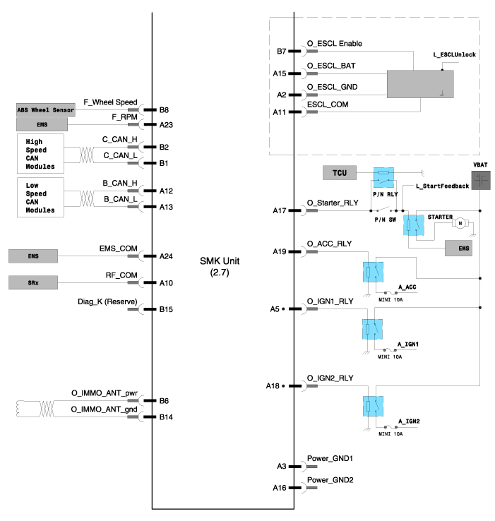
 Hyundai Equus: Smart Key Unit Schematic Diagrams
Second generation VI (2009–2025) / Hyundai Equus VI 2009-2025 Service Manual / Body Electrical System / Smart Key System / Smart Key Unit Schematic Diagrams
Second generation VI (2009–2025) / Hyundai Equus VI 2009-2025 Service Manual / Body Electrical System / Smart Key System / Smart Key Unit Schematic Diagrams
| Circuit Diagram |


 Smart Key Unit Components and Components Location
Components
Connector Pin Information
No.Connector AConnector BConnector C1V_BAT loadC_CAN LowSSB illumination ground2-C_CAN High-3Power ground1-SSB LED OFF4IGN1-Interior antenna #2 power5IGN1 rela ...
 Smart Key Unit Repair procedures
Removal
Smart Key Unit
1.
Disconnect the negative (-) battery terminal.
2.
Remove the crash pad lower panel after loosening the mounting screws.
(Refer to Body - "Crash Pad Lower Panel")
...
See also:
Components and Components Location
Components
1. Door module2. Window glass3. Power window motor4. Outside handle cover 5. Outside handle6. Door panel7. Door checker8. Door striker9. Outside handle pad10. Door striker cover11. Do ...
TPMS Receiver Description and Operation
Description
1.
Mode
(1)
Virgin State
A.
The receiver as a sole part is shipped in this state. Replacement parts should therefore arrive in this state.
B.
In this state, there is no Auto-Lo ...
User Settings Mode
HUD Settings (if equipped)
Display Height
Adjust the height of the HUD image on the windshield glass (Level 0 to 20).
Illumination
Adjust the intensity of the HUD illumination (Level 0 to 20). ...
Categories
Hyundai Equus Manuals
© 2011-2025 Copyright www.heqmanual.com
