 Hyundai Equus: AVN(Audio Video Navigation) head unit Components and Components Location
Second generation VI (2009–2026) / Hyundai Equus VI 2009-2026 Service Manual / Body Electrical System / Premium AVN System / AVN(Audio Video Navigation) head unit Components and Components Location
Hyundai Equus: AVN(Audio Video Navigation) head unit Components and Components Location
Second generation VI (2009–2026) / Hyundai Equus VI 2009-2026 Service Manual / Body Electrical System / Premium AVN System / AVN(Audio Video Navigation) head unit Components and Components Location
Second generation VI (2009–2026) / Hyundai Equus VI 2009-2026 Service Manual / Body Electrical System / Premium AVN System / AVN(Audio Video Navigation) head unit Components and Components Location
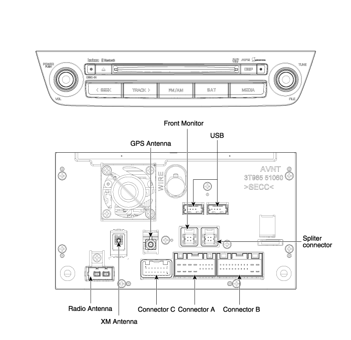
| Components |
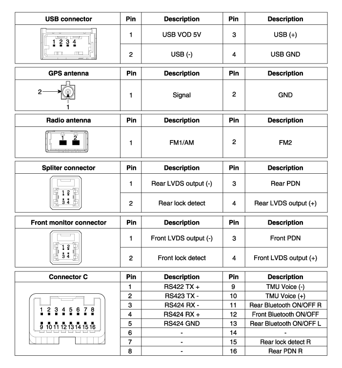
Connector Pin Information
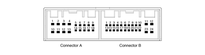
| No. | Connector A | Connector B |
| 1 | - | MM CAN high |
| 2 | Rear camera vedio | - |
| 3 | Rear camera vedio GND | - |
| 4 | - | - |
| 5 | SPDIF GND | - |
| 6 | SPDIF (+) | IGN 1 B(+) |
| 7 | - | AUX video |
| 8 | Illumination (+) | AUX R input |
| 9 | R Position | AUX GND |
| 10 | Rear camera shield GND | Front MIC(+) input |
| 11 | - | ACC B(+) |
| 12 | Navigation voice (-) | B(+) |
| 13 | Navigation voice (+) | MM CAN low |
| 14 | - | - |
| 15 | SPDIF (-) | - |
| 16 | - | Vehicle speed |
| 17 | Illumination (-) | Seering remote GND/Mic GND |
| 18 | Antenna B(+) ON | - |
| 19 | x | AUX video GND |
| 20 | AUX DETECT | |
| 21 | AUX L input | |
| 22 | Front MIC(-) input | |
| 23 | GND | |
| 24 | GND |
 Description and Operation
Description
Premium AVN system
The premium AVN system has improved information search and
easiness of manipulation for the driver by simplifying the system
operation experience and unifying th ...
 AVN(Audio Video Navigation) head unit Repair procedures
Removal
-
Take care not to scratch the center fascia panel and related parts.
-
Eject all the disc before removing the AVN head unit to prevent damaging the DVD player' ...
See also:
Crankshaft Position Sensor (CKPS) Schematic Diagrams
Circuit Diagram
...
Trip Computer Mode
This mode displays driving information like the tripmeter, fuel economy, and
so on.
❈ For more details, refer to “Trip Computer” in this chapter. ...
Middle Speed Sensor Repair procedures
Inspection
1.
Check signal waveform of middle speed sensor using the GDS.
Specification: Refer to "Signal Wave Form" section.
...
Categories
Hyundai Equus Manuals

© 2011-2026 Copyright www.heqmanual.com