 Hyundai Equus: Front Lower Arm Repair procedures
Second generation VI (2009–2025) / Hyundai Equus VI 2009-2025 Service Manual / Suspension System / Front Suspension System / Front Lower Arm Repair procedures
Second generation VI (2009–2025) / Hyundai Equus VI 2009-2025 Service Manual / Suspension System / Front Suspension System / Front Lower Arm Repair procedures
| Removal |
Remove the lateral arm.
| 1. |
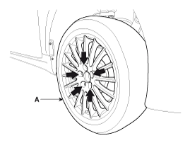
Remove the front wheel and tire (A) from front hub .
|
| 2. |
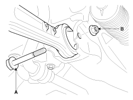
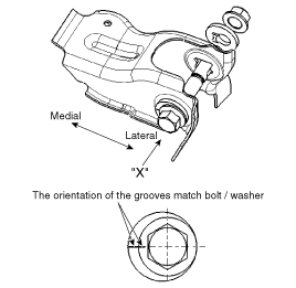
Loosen the flange bolt (A) & lock nut (B).
|
| 3. |
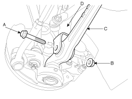
Unscrew the flange bolt (A) and lock nut (B) to disconnect the lateral arm (C) from the strut assembly (D).
|
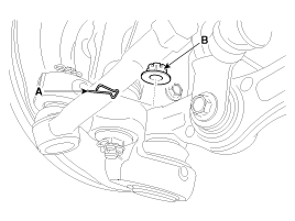
| 4. |
Remove the split pin (A) and castle nut (B).
|
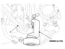
| 5. |
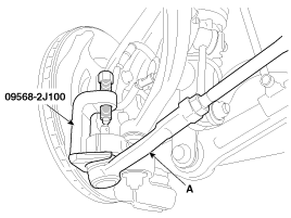
Apply grease to the special tool (09568-2J100), as shown in
the following figure. Then, use the special tool to disconnect the
lateral arm (A) from the knuckle.
|
| 6. |
Install in the reverse order of removal. |
| 7. |
Check the front alignment.
(Refer to Tires/Wheels - "Alignment") |
Remove the tension arm.
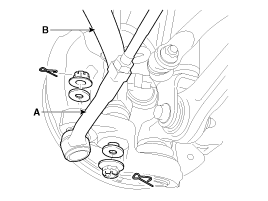
| 1. |
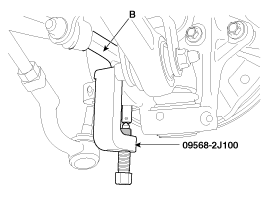
Disconnect the pin and castle nut from the tie-rod end (A) and tension arm (B).
|
| 2. |
Apply grease to the special tool (09568-2J100), as shown in
the following figure. Then, use the special tool to remove the tie-rod
end (A) and tension arm (B) from the knuckle.
|
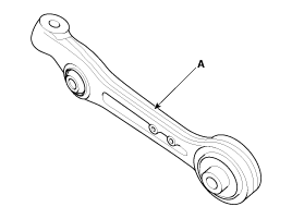
| 3. |
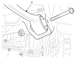
Disconnect the flange bolt and lock nut to remove the tension arm (A) from the frame.
|
| 4. |
Install in the reverse order of removal. |
| 5. |
Check the alignment.
(Refer to Tires/Wheels - "Alignment")
|
| Inspection |
| 1. |
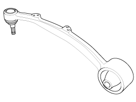
Check the lower arm bushings for damage or signs of aging. If necessary, replace the lower arm assembly. |
| 2. |
Chech the lower arm for deformation. |
| 3. |
Check the all bolts. |
 Front Upper Arm Repair procedures
Removal
1.
Remove the front wheel and tire (A) from front hub .
Tightening torque:
88.3 ~ 107.9 N.m (9.0 ~ 11.0 kgf.m, 65.1 ~ 79.6 lb-ft)
•
Be careful not to dama ...
 Front Stabilizer Bar Repair procedures
Replacement
1.
Removal the front wheel & tire.
Tightening torque :
90.0 ~ 110.0 N.m(9.0 ~ 11.0 kgf.m, 65.0 ~ 80.0 lb-ft)
2.
Disconnect the stabilizer link (A) from the front strut a ...
See also:
Repair procedures
Diagnosis With GDS
1.
BSD system defects can be quickly diagnosed with the GDS. GDS
operates actuator quickly to monitor, input/output value and self
diagnosis.
2.
Connect the cable of GDS ...
Filter replacement
1. With the glove box open, remove the stoppers on both sides to allow the glove
box to hang freely on the hinges.
2. Remove the cylinder at the left of the glove box.
3. Remove the cl ...
Owner maintenance schedule
When you stop for fuel:
Check the engine oil level.
Check coolant level in coolant reservoir.
Check the windshield washer fluid level.
Look for low or under-inflated tires.
WARNING
Be ca ...
Categories
Hyundai Equus Manuals
© 2011-2025 Copyright www.heqmanual.com


