 Hyundai Equus: Master Cylinder Repair procedures
Second generation VI (2009–2024) / Hyundai Equus VI 2009-2024 Service Manual / Brake System / Brake System / Master Cylinder Repair procedures
Hyundai Equus: Master Cylinder Repair procedures
Second generation VI (2009–2024) / Hyundai Equus VI 2009-2024 Service Manual / Brake System / Brake System / Master Cylinder Repair procedures
Second generation VI (2009–2024) / Hyundai Equus VI 2009-2024 Service Manual / Brake System / Brake System / Master Cylinder Repair procedures
| Removal |
| 1. |
Turn ignition switch OFF and disconnect the negative (-) battery cable. |
| 2. |
Remove the cover. |
| 3. |
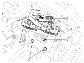
Disconnect the ECM connector (A) and TCM connector (B). And then take the protector of control harness off.
|
| 4. |
Remove the ECM & TCM bracket installation bolts (C) and nut (D). |
| 5. |
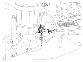
Disconnect the brake fluid level switch connector (A) from the reservoir.
|
| 6. |
Remove the brake fluid from the master cylinder reservoir with a syringe.
|

| 7. |
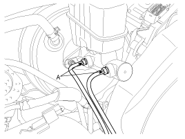
Disconnect the brake tube (B) from the master cylinder by loosening the tube flare nut.
|
| 8. |
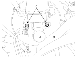
Remove the master cylinder (B) from the brake booster after loosening the mounting nuts (C).
|
| Disassembly |
| 1. |
Remove the reservoir cap and drain the brake fluid into a suitable container. |
| 2. |
Remove the reservoir (C) from the master cylinder (B), after remove mounting screw (A).
|

| 3. |
Remove the retainer ring (A) by using the snap ring pliers. |
| 4. |
Remove the primary piston assembly (B). |
| 5. |
Remove the pin (D) with the secondary piston (C) pushed
completely using a screwdriver. Remove the secondary piston assembly
(C).
|
| Inspection |
| 1. |
Check the master cylinder bore for rust or scratching. |
| 2. |
Check the master cylinder for wear or damage. If necessary, clean or replace the cylinder.
|
| Reassembly |
| 1. |
Apply genuine brake fluid to the rubber parts of the cylinder kit and grommets. |
| 2. |
Carefully insert the springs and pistons in the proper direction. |
| 3. |
Press the secondary piston (C) with a screwdriver and install the cylinder pin (D).
|
| 4. |
Install the retainer ring (A) after installing primary piston assembly (B). |
| 5. |
Mount two grommets (D).
|
| 6. |
Install the reservoir (C) on the cylinder (B), and then install the mounting screw (A). |
| Installation |
| 1. |
Installation is the reverse of removal. |
| 2. |
After installation, bleed the brake system.
(Refer to Brake System - "Brake System Bleeding") |
 Master Cylinder Components and Components Location
Components
1. Reservoir cap2. Reservoir3. Grommet4. Cylinder pin5. Retainer6. Primary piston assembly7. Secondary piston assembly8. Master cylinder body
...
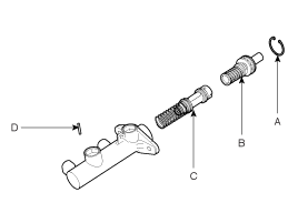
 Brake Line Components and Components Location
Components
...
See also:
Components and Components Location
Component Location
1. Power mirror2. Power mirror switch3. Electrical folding mirror switch
...
Schematic Diagrams
Circuit Diagram
NO.Function1BAT.2IGN3CAN_High4CAN_Low5GND6-
...
Alternator Description and Operation
Description
The Alternator has eight built-in diodes, each rectifying AC current to DC current.
Therefore, DC current appears at alternator "B" terminal.
In addition, the charging voltage of this ...
Categories
Hyundai Equus Manuals

© 2011-2024 Copyright www.heqmanual.com