 Hyundai Equus: ECU Schematic Diagrams
Second generation VI (2009–2024) / Hyundai Equus VI 2009-2024 Service Manual / Suspension System / Air Suspension System / ECU Schematic Diagrams
Hyundai Equus: ECU Schematic Diagrams
Second generation VI (2009–2024) / Hyundai Equus VI 2009-2024 Service Manual / Suspension System / Air Suspension System / ECU Schematic Diagrams
Second generation VI (2009–2024) / Hyundai Equus VI 2009-2024 Service Manual / Suspension System / Air Suspension System / ECU Schematic Diagrams
| Circuit diagram |
| 1. |
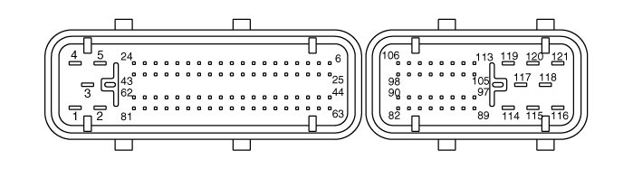
ECU Connector
|
| 2. |
ECU Terminal function
|
 ECU Description and Operation
Description
Analyzes each variety sensor and communication data and executes air suspension control.
That part controls system and maintains function. ...
 ECU Repair procedures
Removal
•
Avoid suffering excessive impact.
•
Do not entering the water into pin inside.
•
Do not pile up the parts.
•
Take care not to damage the pin of ...
See also:
General Information
General
The supplemental restraint system (SRS) is designed to
supplement the seat belt to help reduce the risk or severity of injury
to the driver and passenger by activating and deploying the ...
Components and Components Location
Components Location
1. Head Up Display (HUD)2. HUD switch3. Cluster4. Haptic steerign switch5. Windshield glass (Wedge film applied)6. Light sensor
...
6 Speed Clutch Control Solenoid Valve Schematic Diagrams
Circuit Diagram
...
Categories
Hyundai Equus Manuals

© 2011-2024 Copyright www.heqmanual.com