 Hyundai Equus: Adaptive Front Lighting System Repair procedures
Second generation VI (2009–2024) / Hyundai Equus VI 2009-2024 Service Manual / Body Electrical System / Adaptive Front Lighting System / Adaptive Front Lighting System Repair procedures
Hyundai Equus: Adaptive Front Lighting System Repair procedures
Second generation VI (2009–2024) / Hyundai Equus VI 2009-2024 Service Manual / Body Electrical System / Adaptive Front Lighting System / Adaptive Front Lighting System Repair procedures
Second generation VI (2009–2024) / Hyundai Equus VI 2009-2024 Service Manual / Body Electrical System / Adaptive Front Lighting System / Adaptive Front Lighting System Repair procedures
| Removal |
AFLS Unit
| 1. |
Disconnect the negative (-) battery terminal. |
| 2. |
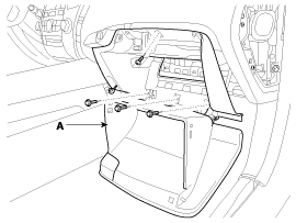
Remove the glove box housing (A). (Refer to the Body group - "Crash pad")
|
| 3. |
Disconnect the glove box housing connector (A).
|
| 4. |
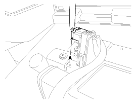
Remove the DIS head unit. (Refer to DIS system) |
| 5. |
Remove the USB interface unit. |
| 6. |
Remove the front/rear parking assist system unit. (Refer to Front/Rear Parking assist system) |
| 7. |
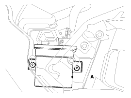
Remove the AFLS unit(A) after removing connector and nuts(2EA).
|
| Installation |
AFLS Unit
| 1. |
Install the AFLS unit after connecting the connector. |
| 2. |
Install the front/rear parking assist system unit. |
| 3. |
Install the USB interface unit. |
| 4. |
Install the DIS head unit. |
| 5. |
Install the glove box housing. |
| 6. |
Connect the negative (-) battery terminal. |
 Adaptive Front Lighting System Description and Operation
Description
AFLS Unit(ECU)
AFLS located in Cockpit Module is provided information of vehicle (steering wheel signal,vehicle speed, inclination of vehicle).
Based on provided information , it calc ...
 Height Sensor Repair procedures
Removal
Height Sensor
1.
Disconnect the negative (-) battery terminal.
2.
Remove the height sensor linkage (A) installed on the front axle and rear axle.
(Number of height sensor : Air suspe ...
See also:
Heater Unit Components and Components Location
Component Location
Components
1. Heater Case (Left)2. Vent Door (Left)3. Temperature Door (Left)4. Floor Door (Left)5. Console Temperature Control Actuator (A) 6. Console Temperature Lever7. Con ...
Electric Parking Brake (EPB) Schematic Diagrams
Circuit Dragram
...
Front Air Strut Assembly Repair procedures
Removal
Air Strut Assembly
•
Before replacing the relevant parts, use GDS equipment to fully discharge the air from the relevant parts.
(Refer to Air Suspension System - ...
Categories
Hyundai Equus Manuals

© 2011-2024 Copyright www.heqmanual.com