 Hyundai Equus: Instrument Cluster Schematic Diagrams
Second generation VI (2009–2024) / Hyundai Equus VI 2009-2024 Service Manual / Body Electrical System / Indicators And Gauges / Instrument Cluster Schematic Diagrams
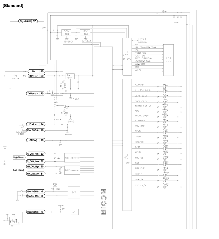
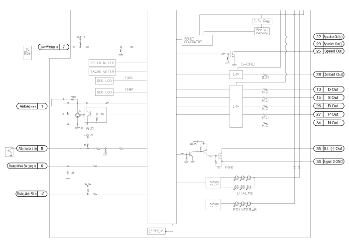
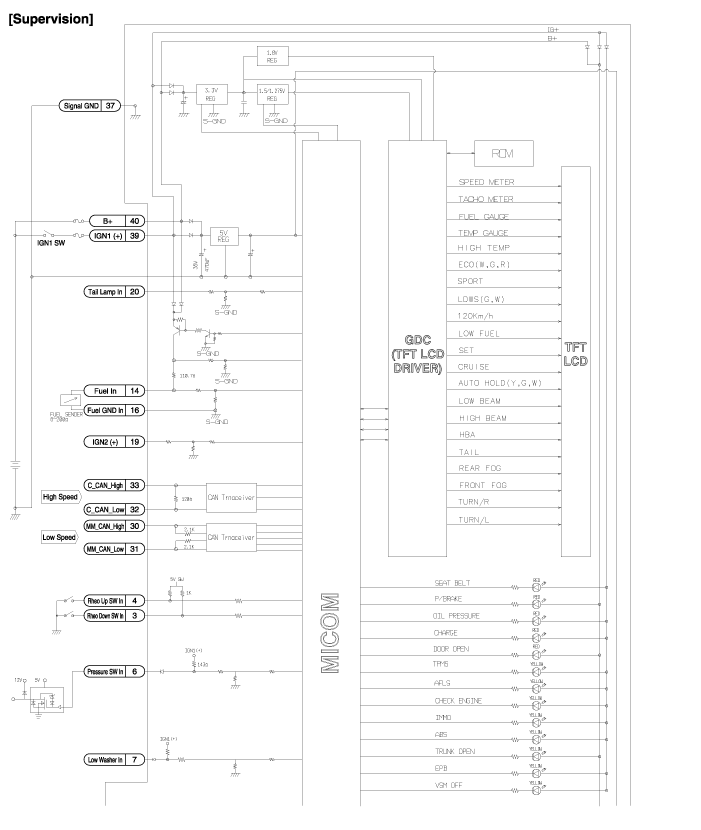
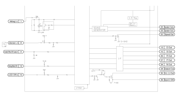
| Circuit Diagram |


 Instrument Cluster Components and Components Location
Components
Connector Pin Information
No.DescriptionNo.Description1Aig bag +21-2-22Speaker +3Rheostat down switch23Speaker -4Rheostat up switch24-5-25Vehicle speed 4P output6Oil pressure26R Output7 ...
 Instrument Cluster Description and Operation
Description
Communication Network Diagram
Refer to the "Body Network System" for the abbreviation information.
Function
1.
High speed CAN communication (C-CAN)
(1)
Use ...
See also:
Auto Defogging Sensor Repair procedures
Inspection
To inspect and diagnose the sensor, refer to Self-Diagnosis procedure and DTC guide.
Replacement
1.
Disconnect the negative (-) battery terminal.
2.
Using a screwdriver or remov ...
Manifold Absolute Pressure Sensor (MAPS) Repair procedures
Inspection
1.
Connect the GDS on the Data Link Connector (DLC).
2.
Measure the output voltage of the MAPS at idle and IG ON.
Specification: Refer to "Specification"
Removal
1.
Tur ...
Front Air Strut Assembly Components and Components Location
Components
1. Air spring2. CDC damper3. Connector4. Air tube connector
1. Insulator cap2. Insulator assembly3. Spring upper pad4. Dust cover5. Bump stopper6. Coil spring7. Shock absorber
...
