 Hyundai Equus: Schematic Diagrams
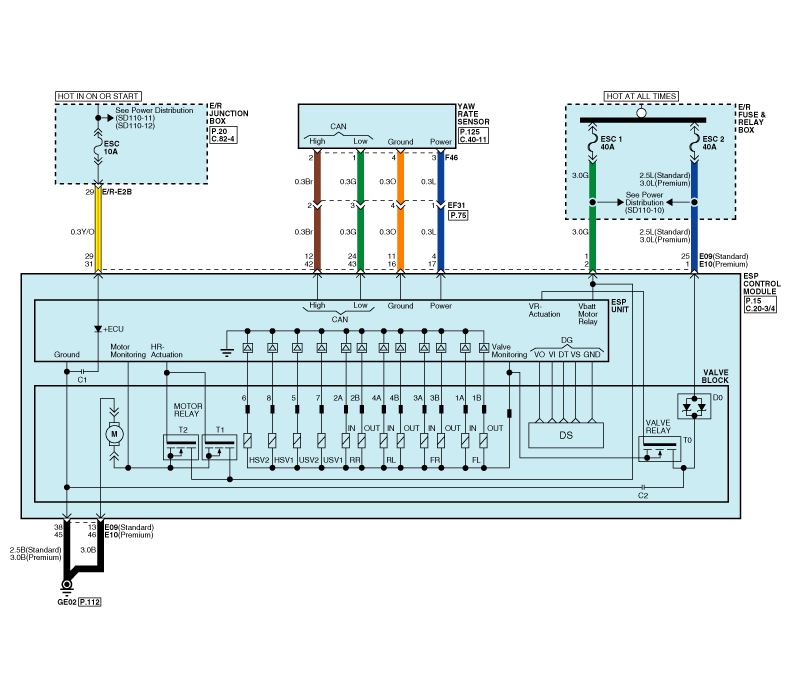
| ESP Circuit Diagram |
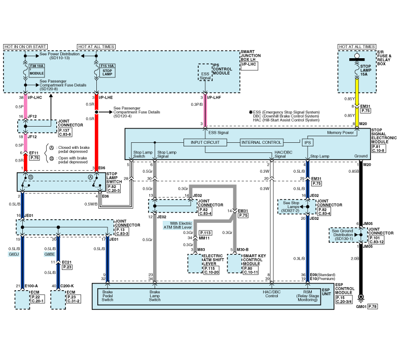
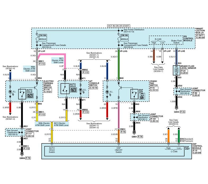
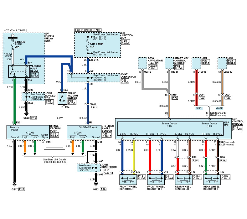
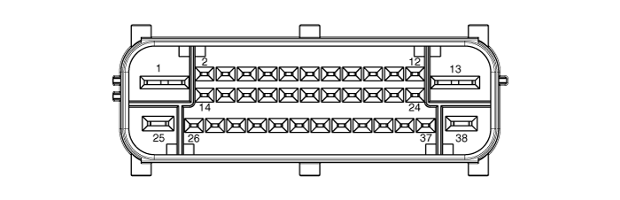
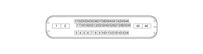
| ESP Connector Input/Output |
| [Standard] |
| [Premium] |
| Connector Terminal | Specification | ||
| Pin No | Description | ||
| Standard | Premium | ||
| 29 | 31 | IGNITION1(+) | High level of wake up voltage : 4.5V < V < 16.0V Low level of wake up voltage : V < 2.4V Max. current : I < 50mA |
| 25 | 1 | POS. BATTERY 1. (SOLENOID) | Over voltage range : 17.0 ± 0.5V Operating voltage range : 10.0 ± 0.5V < V < 16.0 ± 0.5V Low voltage range : 7.0 ± 0.5V < V < 9.5 ± 0.5V Max. current : I < 40A Max. leakage current : I < 0.25mA |
| 1 | 2 | POS. BATTERY 2.(MOTOR) | Operating voltage range: 10.0 ± 0.5V < V < 16.0 ± 0.5V Rush current : I < 110A Max current : I < 40A Max leakage current : I < 0.25mA |
| 38 | 46 | GROUND | Rated current : I <550mA Max. current: I < 40A |
| 13 | 45 | PUMP MOTOR GROUND | Rush current : I < 110A (Standard), I < 140A (Premium) Max current : I < 40A (Standard), I < 60A (Premium) |
| 11 | 16 | SENSOR GROUND | Rated current : I <250mA |
| 4 | 17 | SENSOR POWER | Max current Capability : I < 250mA Max voltage : V_BAT1 -0.8V |
| 23 | 34 | BRAKE LIGHT SWITCH | Input voltage (Low) : V < 2V Input voltage (High) : V > 6V |
| 10 | 18 | ESP ON/OFF SWITCH | Max. Input current : I < 3mA (@12.8V) |
| 9 | 32 | PARKING BRAKE SWITCH | Input voltage (Low) : V < 2V |
| Input voltage (High) : V > 6V | |||
| Max input current : I < 5mA (@12.8V) | |||
| 28 | 27 | FRONT RIGHT WHEEL SPEED OUTPUT | External pull up resistance : 1 Kx < R |
| 17 | 41 | REAR RIGHT WHEEL SPEED OUTPUT | Output duty :50 ± 20% |
| 14 | 15 | CAN BUS LINE(LOW) | Max. Input current : I < 10mA |
| 26 | 14 | CAN BUS LINE(HIGH) | |
| 18 | 4 | SENSOR FRONT LEFT POWER | Output voltage : V_BAT1 -0.6V ~ V_BAT1 -1.1V Output current : Max 30mA |
| 34 | 5 | SENSOR FRONT RIGHT POWER | |
| 19 | 7 | SENSOR REAR LEFT POWER | |
| 33 | 6 | SENSOR REAR RIGHT POWER | |
| 31 | 9 | SENSOR FRONT LEFT SIGNAL | Input current LOW : 5.9 ~ 8.4mA Input current HIGH : 11.8 ~ 16.8mA Frequency range : 1 ~ 2500Hz Input duty : 50 ± 10% |
| 21 | 10 | SENSOR FRONT RIGHT SIGNAL | |
| 32 | 12 | SENSOR REAR LEFT SIGNAL | |
| 20 | 11 | SENSOR REAR RIGHT SIGNAL | |
| 12 | 42 | CAN SENSOR LINE (HIGH) | Max. input current : I < 10mA |
| 24 | 43 | CAN SENSOR LINE (LOW) | |
| 8 | 39 | HAC RELAY DRIVE | Max. Current : I< 180mA Max.Output Low Voltage : V< 1.2V |
| 36 | 19 | RELAY STATE MONITORING | Input voltage (Low) : V < 2V Input voltage (High) : V > 6V Max. Input current : I < 10mA (@ 12.8V) |
 Description and Operation
Description of ESP
Optimum driving safety now has a name: ESP, the Electronic Stability Program.
ESP recognizes critical driving conditions, such as panic
reactions in dangerous situations, a ...
 Troubleshooting
Failure Diagnosis
1.
In principle, ESP and TCS controls are prohibited in case of ABS failure.
2.
When ESP or TCS fails, only the failed system control is prohibited.
3.
However, when the ...
See also:
Front Seat Shield Inner Cover Components and Components Location
Component Location
1. Front seat shield inner cover
...
Cylinder Head Repair procedures
Removal
•
Use fender covers to avoid damaging painted surfaces.
•
To avoid damaging the cylinder head, wait until the engine
coolant temperature drops below normal ...
Camshaft Position Sensor (CMPS) Troubleshooting
Signal Waveform
This example shows a typical Crankshaft Position Sensor (CKPS) and Camshaft Position Sensor (CMPS) waveform at idle. ...
Categories
Hyundai Equus Manuals

© 2011-2024 Copyright www.heqmanual.com