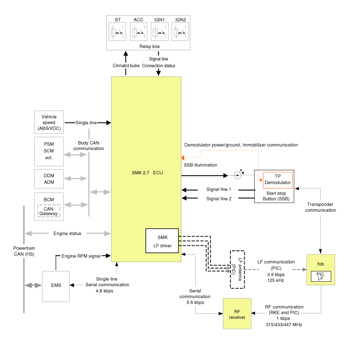
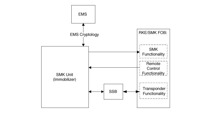
 Hyundai Equus: Schematic Diagrams
| Circuit Diagram (1) |

| Circuit Diagram (2) |

 Components and Components Location
Component Location
1. Start Stop Button(SSB)2. FOB key3. Trunk open switch4. RF receiver5. Interior antenna 16. Interior antenna 27. Interior antenna 38. Trunk antenna9. Door handle & do ...
 Description and Operation
Description
System Overview
The System offers the following features:
-
Human machine interface through a 1-stage button, for terminal switching and engine start.
-
Control of external re ...
See also:
Compressor Schematic Diagrams
Circuit diagram
1.
Air compressor connector
[Motor power connector (A)][Exhaust valve connector (B)][Temperature sensor connector (C)]
2.
Air compressor terminal function
[Motor power]
...
Fuel Pressure Control Valve Schematic Diagrams
Circuit Diagram
...
Compass Mirror Description and Operation
Description
The compass feature is designed to be integrated into an electro chromic interior rearview mirror.
The mirror assembly shall display a compass heading.
The compass mirror then take th ...
Categories
Hyundai Equus Manuals
© 2011-2024 Copyright www.heqmanual.com
