 Hyundai Equus: Rear Upper Arm Repair procedures
Second generation VI (2009–2025) / Hyundai Equus VI 2009-2025 Service Manual / Suspension System / Rear Suspension System / Rear Upper Arm Repair procedures
Second generation VI (2009–2025) / Hyundai Equus VI 2009-2025 Service Manual / Suspension System / Rear Suspension System / Rear Upper Arm Repair procedures
| Removal |
| 1. |
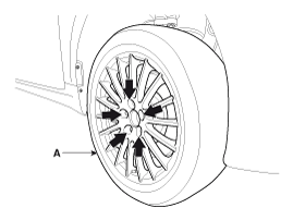
Remove the rear wheel and tire (A) from rear hub .
|
| 2. |
Support the lower portion of the rear axle with a jack securely. |
| 3. |
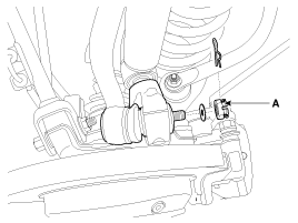
Remove the split pin and castle nuts (A).
|
| 4. |
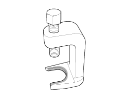
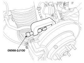
Disconnect the rear upper arm (A) with the rear carrier using a SST (09568-2J100).
|
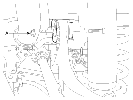
| 5. |
Loosen the flange bolt & lock nuts (A).
|
| 6. |
Installation is the reverse of removal.
|
| 7. |
Check the alignment.
(Refer to Tires/Wheels - "Alignment") |
| Inspection |
| 1. |
Check the bushing for wear and deterioration. |
| 2. |
Check the ball joint for rotating torque. |
 Rear Shock Absorber Repair procedures
Removal
1.
Remove the rear wheel and tire (A) from rear hub .
Tightening torque:
88.3 ~ 107.9 N.m (9.0 ~ 11.0 kgf.m, 65.1 ~ 79.6 lb-ft)
•
Be careful not to damage ...
 Rear Assist Arm Repair procedures
Removal
1.
Remove the rear wheel and tire (A) from rear hub .
Tightening torque:
88.3 ~ 107.9 N.m (9.0 ~ 11.0 kgf.m, 65.1 ~ 79.6 lb-ft)
•
Be careful not to damage ...
See also:
ETC (Electronic Throttle Control) System Schematic Diagrams
Circuit Diagram
...
Fuel Filler Door Release Actuator Repair procedures
Inspection
1.
Remove the trunk room left side trim.
2.
Open the fuel filler door and remove the housing.
(Refer to the BD group - "Exterior")
Do not reuse the fuel fill ...
Starter Schematic Diagrams
Circuit Diagram
...
Categories
Hyundai Equus Manuals
© 2011-2025 Copyright www.heqmanual.com


