Throttle Position Sensor (TPS)
| 1. |
Connect the GDS on the Data Link Connector (DLC). |
| 2. |
Start the engine and measure the output voltage of TPS 1 and 2 at C.T. and W.O.T.
Throttle angle(°)
| Output Voltage (V)
| TPS1
| TPS2
| C.T
| 0.5
| 4.5
| W.O.T
| 4.41
| 0.59
|
|
ETC Motor
| 1. |
Turn the ignition switch OFF. |
| 2. |
Disconnect the ETC module connector. |
| 3. |
Measure resistance between the ETC module terminals 1 and 2. |
| 4. |
Check that the resistance is within the specification.
Specification: Refer to “Specification”
|
|
| 1. |
Turn the ignition switch OFF and disconnect the battery negative (-) cable. |
| 2. |
Remove the resonator and the air intake hose (Refer to “Intake And Exhaust System” in EM group). |
| 3. |
Disconnect the ETC module connector (A). |
| 4. |
Remove the installation bolts (B), and then remove the ETC module (C) from the engine. 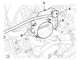
|
| • |
Install the component with the specified torques. |
| • |
Note that internal damage may occur when the component is dropped. If the component has been dropped, inspect before installing. |
|
| 1. |
Install in the reverse order of removal.
Electronic throttle body Installation bolt:
7.8 ~ 9.8 N.m (0.8 ~ 1.0 kgf.m, 5.8 ~ 7.2 lb-ft)
|
|
| ETC module learning procedure |
When installing new ETC module or re-installing it, ETC module learning procedure must be performed.
| 1. |
Hold the ignition key or the start button at th IG ON position during 5 seconds. |
| 2. |
Turn ignition swich OFF and then start the engine. |
|
DTC codes (P0638, P2110) might be displayed if ETC module learning procedure does not performed after replacing ETC module. |
Description
Manifold Absolute Pressure Sensor (MAPS) is a speed-density
type sensor and is installed on the surge tank. It senses absolute
pressure of the surge tank and transfers the analog si ...
See also:
Driver Airbag (DAB) Module and Clock Spring Description and Operation
Description
The Driver Airbag (DAB) is installed in the steering wheel
and electrically connected to SRSCM via the clock spring. It protects
the driver by deploying the airbag when frontal cras ...
Information Mode
Service Interval
This mode shows the service interval (mileage and days).
❈ For the setting of the service interval, refer to "User Settings Mode" of
the LCD display.
Service in
...
Electronic stability control (ESC)
The Electronic Stability control (ESC) system is designed to stabilize the vehicle
during cornering maneuvers. ESC checks where you are steering and where the vehicle
is actually going. ESC ap ...
 Hyundai Equus: ETC (Electronic Throttle Control) System Repair procedures
Second generation VI (2009–2026) / Hyundai Equus VI 2009-2026 Service Manual / Engine Control/Fuel System / Engine Control System / ETC (Electronic Throttle Control) System Repair procedures
Hyundai Equus: ETC (Electronic Throttle Control) System Repair procedures
Second generation VI (2009–2026) / Hyundai Equus VI 2009-2026 Service Manual / Engine Control/Fuel System / Engine Control System / ETC (Electronic Throttle Control) System Repair procedures

 ETC (Electronic Throttle Control) System Schematic Diagrams
 Manifold Absolute Pressure Sensor (MAPS) Description and Operation