
 Hyundai Equus: Heater Unit Components and Components Location
Second generation VI (2009–2026) / Hyundai Equus VI 2009-2026 Service Manual / Heating, Ventilation and Air Conditioning / Heater / Heater Unit Components and Components Location
Hyundai Equus: Heater Unit Components and Components Location
Second generation VI (2009–2026) / Hyundai Equus VI 2009-2026 Service Manual / Heating, Ventilation and Air Conditioning / Heater / Heater Unit Components and Components Location
Second generation VI (2009–2026) / Hyundai Equus VI 2009-2026 Service Manual / Heating, Ventilation and Air Conditioning / Heater / Heater Unit Components and Components Location
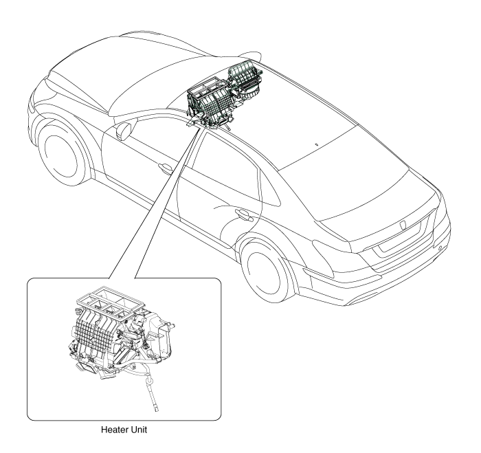
| Component Location |
| Components |
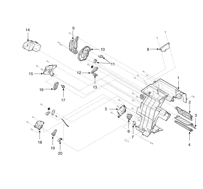
| 1. Heater Case (Left) 2. Vent Door (Left) 3. Temperature Door (Left) 4. Floor Door (Left) 5. Console Temperature Control Actuator (A) 6. Console Temperature Lever 7. Console Temperature Arm 8. Vent Guide 9. Mode Control Actuator 10. Mode Cam | 11. Vent Door Arm 12. Floor Door Lever 13. Floor Door Arm 14. Shower Duct 15. Temperature Control Actuator (Driver's side) 16. Temperature Door Lever (Driver's side) 17. Temperature Door Arm (Driver's side) 18. Console Temperature Control Actuator 19. Console Temperature Lever 20. Console Temperature Arm |
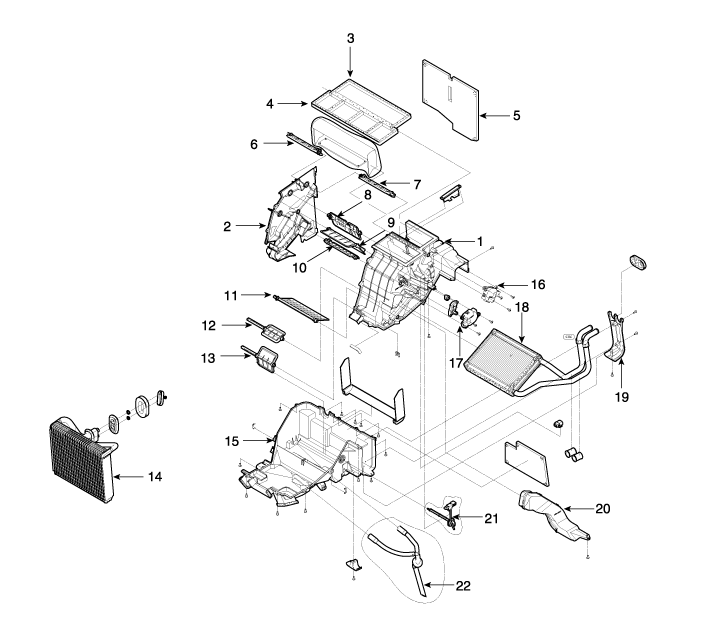
| 1. Heater Case (Right) 2. Seperator 3. Center Duct Seal 4. Center Duct Seal 5. Insulator 6. Def Door (Left) 7. Def Door (Right) 8. Vent Door (Right) | 9. Temperature Door (Right) 10. Floor Door (Right) 11. Console Temperature Door 12. Console Temperature Door (A) 13. Console Mode Door 14. Evaporator Core 15. Heater Lower Case 16. Auto Defogging Actuator | 17. Temperature Control Actuator (Passenger's side) 18. Heater Core 19. Heater Core Cover 20. Shower duct 21. Evaporator Temperature Sensor 22. Drain Hose |
 Heater
...
 Heater Unit Repair procedures
Replacement
1.
Disconnect the negative (-) battery terminal.
2.
Recover the refrigerant with a recovery/recycling/charging station.
3.
When the engine is cool, drain the engine coolant fro ...
See also:
Reprogramming a single HomeLink® button
To program a device to HomeLink® using a HomeLink® button previously trained,
follow these steps:
1. Press and hold the desired HomeLink® button. DO NOT release the button.
2. The indicator lig ...
Head Up Display Unit Repair procedures
Removal
1.
Disconnect the negative (-) battery terminal.
2.
Remove the head up display bezel (A).
3.
Remove the instrument cluster.
(Refer to Indicators And Guages - "Instrument Cluster") ...
Center Pillar Trim Repair procedures
Replacement
[Center Pillar Lower Trim]
•
Put on gloves to protect your hands.
•
When prying with a flat-tip screwdriver, wrap it with
...
Categories
Hyundai Equus Manuals

© 2011-2026 Copyright www.heqmanual.com