 Hyundai Equus: AVN Antenna Repair procedures
Second generation VI (2009–2026) / Hyundai Equus VI 2009-2026 Service Manual / Body Electrical System / Premium AVN System / AVN Antenna Repair procedures
Hyundai Equus: AVN Antenna Repair procedures
Second generation VI (2009–2026) / Hyundai Equus VI 2009-2026 Service Manual / Body Electrical System / Premium AVN System / AVN Antenna Repair procedures
Second generation VI (2009–2026) / Hyundai Equus VI 2009-2026 Service Manual / Body Electrical System / Premium AVN System / AVN Antenna Repair procedures
| Inspection |
Glass Antenna Test
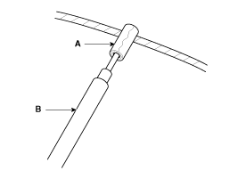
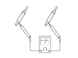
| 1. |
Wrap aluminum foil (A) around the tip of the tester probe (B) as shown.
|
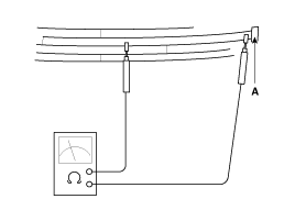
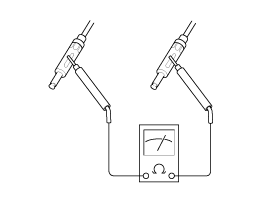
| 2. |
Touch one tester probe to the glass antenna terminal (A) and
move the other tester probe along the antenna wires to check that
continuity exists.
|
Glass Antenna Repair
To make an effective repair, the broken section must be no longer than one inch. |

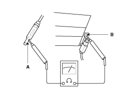
| 1. |
Lightly rub the area around the broken section (A) with fine steel wool, and then clean it with alcohol.
|
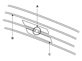
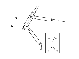
| 2. |
Carefully mask above and below the broken portion of the glass antenna wire (B) with cellophane tape (C). |
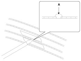
| 3. |
Using a small brush, apply a heavy coat of silver conductive
paint (A) extending about 1/8xon both sides of the break. Allow 30
minutes to dry.
|
| 4. |
Check for continuity in the repaired wire. |
| 5. |
Apply a second coat of paint in the same way. Let it dry three hours before removing the tape. |
Glass Antenna Circuit Inspection
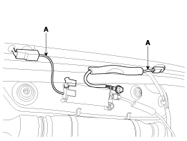
| 1. |
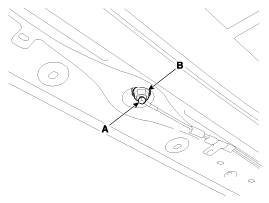
Remove the left side rear quarter trim (B) after opening the cap (A) and loosening the screw.
|
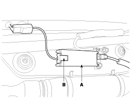
| 2. |
Disconnect the antenna feeder cable (B) from the glass antenna amp (A).
|
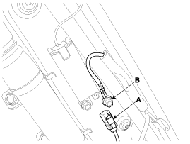
| 3. |
Turn the radio ON.
Measure the voltage between terminal of the harness side feeder cable (A) and body ground (B).
|
| 4. |
Disconnect the 2P connector of radio wiring from the glass antenna amp. |
| 5. |
Check for continuity between terminals of harness side connector and antenna grid terminals (A).
|
| 6. |
Check the grid lines for continuity. |
| 7. |
When a poor radio reception is not repaired through the above inspection methods, replace the amp.
If the radio reception is still poor, check the radio cable for short and radio head unit for failure. |
Antenna Cable
| 1. |
Check for continuity between the center poles of antenna cable.
|
| 2. |
Check for continuity between the outer poles of antenna cable. There should be continuity.
|
| 3. |
If there is no continuity, replace the antenna cable. |
| 4. |
Check for continuity between the center pole (A) of antenna cable and terminal of glass antenna (B). There should be continuity.
|
| 5. |
If there is no continuity, replace the antenna amplifier. |
| 6. |
Check for continuity between the center pole (A) and outer pole (B) of antenna cable. There should be no continuity.
|
| 7. |
If there is continuity, replace the antenna cable. |
| Removal |
| 1. |
Disconnect the negative (-) battery terminal. |
| 2. |
Remove the roof trim.
(Refer to Body - "Roof Trim Assembly") |
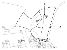
| 3. |
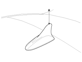
Remove the roof antenna (A) after loosening a nut (B).
|
| Installation |
| 1. |
Connect the roof antenna connectors. |
| 2. |
Install the rear roof trim.
|
 AVN Antenna Components and Components Location
Components
...
 Speakers Repair procedures
Inspection
1.
Troubleshooting for Speaker
(1)
Basic inspection of speaker
Inspect the sound from speaker after verifying that the
speaker mounting screws are removed and the wiring connector ...
See also:
Injector Troubleshooting
Signal Waveform
...
Cup holder
WARNING - Hot liquids
Do not place uncovered cups of hot liquid in the cup holder while the
vehicle is in motion. If the hot liquid spills, you could be burned. Such a
burn to the driver cou ...
Repair procedures
EOL Input
Description
When shift shock is occurred or parts related with the transmission are replaced, EOL should be performed.
In the following case, EOL is required.
•
Transmission ass ...
Categories
Hyundai Equus Manuals

© 2011-2026 Copyright www.heqmanual.com